RH Universal / Just a thought.
Looking at the RH amps..I want to see what people think.
Theoretical amp build..
RH style schade FB lets say 100k.
Diode cathode bias on the driver tube 12AT7.
Switching for Triode/Pentode/UL 1K grid stopper on Grid 2 (No Zener)
Cathode of output tube biased with LM317T CCS. (Tube rolling)
Cathode of Output tube bypass cap connected to Gnd via output Tx secondary.
So its similar to the RH universal with a few differences..
Regards
M. Gregg
Last edited:
Well,
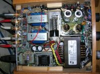
I converted an existing amp,
Its very similar to the RH universal..
1K on G2 no zener just for fun..
Diode cathode bias on driver tube..
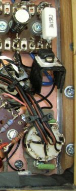
And fitted a rotary switch...The triode connection was quite nice, however the gain was a bit low so I thought how could I better use the three position 4 pole rotary switch to better effect...the result is position 1 is Schade (RH) feedback in U/L with 200K for the ECC83/ECC82...position 2 is schade in U/L with 100K for ECC81/12at7...position 3 is pentode with 12at7 and 100K FB. Or position 1 with 12 AT7 and more gain..")
The output transformer secondary has to be in the correct phase..and it seems to work quite well..
The 317T is in CCS with 15 Ohm resistor. KT66/EL34/6l6..etc
So there you go..pic is rotary switch set up..Obviously you can't switch it with the amp powered up..well you can but the speakers take a bit of a thump..LOL
Regards
M. Gregg
I converted an existing amp,
Its very similar to the RH universal..
1K on G2 no zener just for fun..
Diode cathode bias on driver tube..
And fitted a rotary switch...The triode connection was quite nice, however the gain was a bit low so I thought how could I better use the three position 4 pole rotary switch to better effect...the result is position 1 is Schade (RH) feedback in U/L with 200K for the ECC83/ECC82...position 2 is schade in U/L with 100K for ECC81/12at7...position 3 is pentode with 12at7 and 100K FB. Or position 1 with 12 AT7 and more gain..
The output transformer secondary has to be in the correct phase..and it seems to work quite well..
The 317T is in CCS with 15 Ohm resistor. KT66/EL34/6l6..etc
So there you go..pic is rotary switch set up..Obviously you can't switch it with the amp powered up..well you can but the speakers take a bit of a thump..LOL
Regards
M. Gregg
Attachments
Last edited:
RH amps,
Apparently its supposed to mean "racing horse"..
RH Amplifiers: RH Universal v.2 – Totally Universal
I am using 150K in the driver anode and .9V diode cathode bias, grid grounding is 1M and grid stopper is 22K (before the 1M)..However my B+ is only 275V-280V with hexfred rectifier. Coupling cap is 0.1uF instead of .22uF.
It was just something I wanted to try.
Regards
M. Gregg
Last edited:
Yikes! All this time I thought it was referring to the designs from the RCA Radio Handbook.
Jp
That was my fist thought but that is usually referred to as RDH isn't it?
Cheers
Ian

A 47V zener has been fitted in series with the 1K on grid 2 with rotary SW in position1 and 3,
As per RH universal Value and type
Bzt03c47 3.25w Zener Diode
Position 1 on the rotary switch is now 200K FB with connection pentode via zener and 1K for ECC83 and ECC82.
Other positions are as before
Pos 2 U/L 100K FB for 12AT7
Pos 3 pentode RH zener/1K and 100K FB for 12AT7...(Led Zeppelin 2 CD)..
Its running quite well at the moment..
Regards
M. Gregg
Last edited:
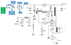
Howz 'bout a hand drawn schematic showing what you've done..
Well scribble done,
Its still in play mode, however...
..the reg is going to be changed..for a start...LOLI might change the one position so I get pentode via 1K to B+ without the zener..just for fun..
(the one linked to the zener on the circuit)Coupling cap is still 0.1uF..the connection to the UL OPtx connection could be connected to triode etc if there was no UL connection on the OP Tx..
NB the rotary sw has a plastic shaft so there is isolation between the knob and the switch..rated a 500V..etc (nothing special just silver contacts maplin do them)
Regards
M. Gregg
Attachments
Last edited:
Well I haven't got around to trying the reg change yet..
I have just been listening..and I am quite surprised..
Just some info for anyone interested..
it still has the LM317t in the cathode at the moment.
The diodes in the cathode are 1n4007 (ground side) and a schottky (under the cathode) to give app .95V drop.
The FB resistors are kiwame (100K X2)
And the other resistors are tantalum with just the input 22K Takman MF I just had some..
The PSU is a Fred diode bridge with 10H choke bypassed with 47N polyester 600V cap.
I am running 12at7 at the moment with 6l6... (lighthouse family)
Still playing with it at the moment... you know where you get to the point when its nice to listen to it..
Regards
M. Gregg
I have just been listening..and I am quite surprised..
Just some info for anyone interested..
it still has the LM317t in the cathode at the moment.
The diodes in the cathode are 1n4007 (ground side) and a schottky (under the cathode) to give app .95V drop.
The FB resistors are kiwame (100K X2)
And the other resistors are tantalum with just the input 22K Takman MF I just had some..
The PSU is a Fred diode bridge with 10H choke bypassed with 47N polyester 600V cap.
I am running 12at7 at the moment with 6l6...
(lighthouse family)Still playing with it at the moment... you know where you get to the point when its nice to listen to it..
Regards
M. Gregg
I have also found that members of the family are swapping the amps over,
And they sort of forget that its not a computer..
twice I have seen them power an amp with the speakers connected to a different one..
So all my amps now have a permanent resistor (inside) across the speaker output terminals for safety....Its nice they like to listen to them....
Plug and play I guess..I will probably have to make a preamp with amp output select that changes the speakers over with the input..
Regards
M. Gregg
And they sort of forget that its not a computer..
twice I have seen them power an amp with the speakers connected to a different one..
So all my amps now have a permanent resistor (inside) across the speaker output terminals for safety..
..Its nice they like to listen to them....Plug and play I guess..I will probably have to make a preamp with amp output select that changes the speakers over with the input..
Regards
M. Gregg
Last edited:
For interest,
I have just run a 7025 as the driver and it sounds very good..
The diode bias seems to pull the image into the centre no matter what tube you use..with the resistor in place it shifts dependant on section gain.
So the diodes stay in..
Regards
M. Gregg
I have just run a 7025 as the driver and it sounds very good..
The diode bias seems to pull the image into the centre no matter what tube you use..with the resistor in place it shifts dependant on section gain.
So the diodes stay in..
Regards
M. Gregg
Last edited:
- Status
- This old topic is closed. If you want to reopen this topic, contact a moderator using the "Report Post" button.
- Home
- Amplifiers
- Tubes / Valves
- Just a thought.