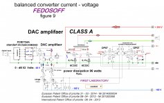
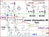
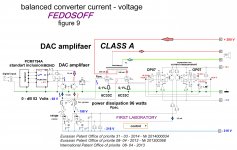
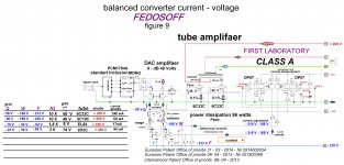
Dear Colleagues. I propose to discuss the universal scheme of top-end tube amplifier PP. Description to Figure 9. Currently, digital media is a major source of information practically . There are new digital formats with high resolution. Moreover the process of recording , mixing, mastering , takes place in the digital environment. And the concept of analog amplification was laid decades ago and has not changed . Correctors , equalizer , preamplifiers , power amplifiers , do not forget operational amplifiers directly to CD or DVD device. That is a common analog amplification path consists of many electronic parts - resistors, transistors, capacitors , transformers, respectively, included in series. In addition, proofreaders , equalizer , preamplifiers , power amplifiers connected in series interblock connectors. This so-called - the method of successive amplification of sound signals , clearly exhausted itself , as each electronic component is a loss of particles information. In general, a result significantly affected micro dynamics and overtones. Obviously, it was time to change the ideology of building all the amplification path . To do this, proposed to abandon the usual sequential method of amplifying audio signals and integrate directly into the DAC chip power amp . This will significantly reduce the length of the sound of the analog section , and all the signal correction carried out directly in a digital device . Figure 9 shows a push-pull output stage . The scheme is universal. Reduced scheme ( denominations details) " sharpened " under lamp 6S33S . However possible to use almost any output tubes until GM70 . To go to other lamps required - select the operation mode of the output tubes . Next, choose a specific lamp voltage grid bias , the magnitude of the AC voltage applied to the grid lamps and P1 respectively trimmer to set the desired quiescent current . In this scheme, it is very simple . A feature of this scheme is that the input of the output stage is fed precisely balanced differential signal High level directly from the chip DAC ( RSM1794A ) . In this topology, the output push-pull stages of construction it is possible to completely eliminate operational amplifiers directly to CD or DVD device to eliminate extra gain stages , and also the most difficult stage is implemented - analog phase inverter. Also, when constructing a topology excluded interconnect couplers. DAC chip RSM1794A directly integrated into the amplifier and switched to mono , for greater impact current and to improve linearity. With the digital zero , the current flowing from RSM1794A is 13 mA. In the emitters of transistors T1, T2 directly from the DAC chip RSM1794A served arising variable (sound) current ( + - 5 mA at 0 dB). The effluent from the alternating current of the transistor T3, aka current DAC chip RSM1794A , create a variable audio voltage across the resistor R1 and R3. The level of AC voltage is determined by resistors R1 and R3. Push-pull output stage , built on a powerful low-impedance tubes 6S33S , however, possible to use other lamps , as specified above. The level of the AC output voltage is determined by the resistor R1 . In place of the resistor R1 can install stair level control . In place of a single volume control scheme can be set frequency-dependent volume control or combined passive node volume and tone adjustments . Adjusting the volume at the same time - analog , digital and robot over SPDIF. Digital volume is set to maximum. Robot adjustable analog. In the push-pull output stages of the level determined by the precision harmonic currents in the windings and the magnitude of the AC voltage on the primary windings of the transformer sound . Balance alternating voltage is set by trimmer P3. Current balance is maintained machine. Current balance in the output stage is achieved by changing the negative grid voltage . Current of each lamp is individually and automatically . Scheme current setting for each lamp comprises an operational amplifier , a bipolar transistor and a field , and measuring the resistance . Measuring the resistance value is small and is included in the cathode circuit of the lamp. In operation, the amplifier circuitry automatically compares the reference voltage and the voltage taken from the measuring resistor and adjusting the cathode potential . Balance scheme operates as follows. Assume that the current of the lamp L1 is bigger now. Voltage at the measuring resistance becomes larger than the reference . The output voltage of the comparator is reduced , the current through the transistor T6 decrease. Also decrease the voltage drop across the resistor R17. As a result, at the source of the FET T3 to increase the negative voltage . This voltage is applied to the control grid lamp L1 . Current balance will be restored. Choke DR1 and Ap2 included in the collector circuit of transistors T1 and T2 are used for noise suppression on digital . Dignity scheme - easy , no capacitors in the cathode lamp circuit , automatic balance adjustment current balance adjustment alternating voltage across the primary winding of the transformer , the shortest path ( the shortest in the world) . Receipt of any large-scale conversion factor . Significant reduction of intermodulation distortion . The absence of feedback , dynamic distortion and phase shift , coupling capacitors and connectors interconnect . Substantial suppression of harmonics in the output transformer due to the accurate balance of current and voltage . Hence the most correct ( reliable ) sound. Applied chips - PCM1794A x 2 generator SIT5001, receiver WM8804. Four low-noise stabilizer 5.5 volts. Four low-noise stabilizer 3.3 volts . Amplifier international application was filed under the PCT, with a priority of 08 - 04 - 2013. In this branch will gradually added new development. Further, this thread will be gradually added new development. Sincerely .
Attachments
Last edited:
How can that be ?
Mona
Perhaps no coincidence denominations. However, the scheme works video here ??????????? ???????????? ???????????. ?????2 - YouTube Yours.
Shure,with bias -130V pure class B. If not explain the voltages in that schematic ??
Mona
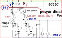
Updated calculation. Fixed bugs in the resistors and voltages. Operates in class A.
Attachments
Um... If this circuit is patented, we will all commit patent infringement if we reproduce it.
It's an application, not a granted patent. And, of course, even with a patent, you're allowed to build examples for experimental or investigative purposes.
It's an application, not a granted patent. And, of course, even with a patent, you're allowed to build examples for experimental or investigative purposes.
Dear Colleagues, it is possible to construct for home use and for research.
Poblems,problems,...
How are your calculation scills ?
Mona
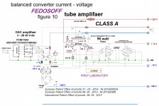
When calculating the modes should proceed from the following. 1 Volt AC voltage 215-ohms.
The amplifier is possible to use almost any output tubes from 6P3S to GU80 . In the diagram on the left side , there is a table with which it is possible to choose the lamp mode independently. From the practice - when calculating modes should proceed from the following . RSM1794A - include in MONO . For AC output voltage V 1 requires 215- ohm resistor . Choose, for a specific lamp , anode voltage, grid bias , the magnitude of the AC voltage applied to the grid lamps and P2 respectively trimmer set the desired quiescent current .
Attachments
Hello Roren. Table is an example of self-analysis. You can choose your own. Now this thread I adding new development. Sincerely.Hi, Fedosoff.
I think the schematic looks interesting. I don't have the knowledge to cirtisise it. I
just find it interesting. In the table for different tubes I see that you run the EL84
with only 17mA. Why so low?
Thank you for charing your ideas.
PCM1794: the name comes from Pulse Code Modulation, I suppose. Russian P read latin R, Russian C read latin S, RSM1794 read PCM1794I hope the amplifier works better... Patent officers never build the submitted idea. How is volume control realized?
Scheme and the volume control works fine. Sincerely.
Attachments

OK, I got it.FEDOSOFF said:Hello Roren. Table is an example of self-analysis. You can choose your own. Now this thread I adding new development. Sincerely.
Is it P2? The pot that is AC coupled between the two balanced lines?Scheme and the volume control works fine. Sincerely.
I am not saying your schem doesn't work, I am just trying to understand.
Is it P2? The pot that is AC coupled between the two balanced lines?
I am not saying your schem doesn't work, I am just trying to understand.
Hello Roren. AC voltage in the same branches. DC voltage in different branches. Capacitor C14 impedes the flow of DC and AC voltage passes Yours.
- Status
- This old topic is closed. If you want to reopen this topic, contact a moderator using the "Report Post" button.
- Home
- Amplifiers
- Tubes / Valves
- The sensation of the 21st Century. Galvanic SUPER HIGH END PP power for all types of