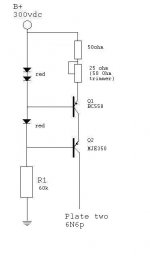
The "upper" transistor (the one with the pot and resistor in the emitter circuit) doesn't see much voltage or needs to dissipate power, so you can do much better by using a lower voltage higher and hfe type.
Likewise, you get higher output impedance with a larger emitter resistor, so it could be worthwhile to series a pair of red LEDs for the reference to get you 3.3-3.4V or so, and resize the resistors accordingly.
Likewise, you get higher output impedance with a larger emitter resistor, so it could be worthwhile to series a pair of red LEDs for the reference to get you 3.3-3.4V or so, and resize the resistors accordingly.

Load Line Questions
I have a couple load line questions. First, when you draw a load line you want to, if possible, stay above the curved lower section of the lines. Is that correct? As I understand it the curved sections represent distortion. And with a constant current source the load line is a horizontal flat line. So I would want to choose a current that puts the line above the curves but below the dissipation line limit? Also, at rest the bias point will be at the intersection of the CCS line and the B+ without a signal. With a signal applied (positive voltage) the bias point will slide back and forth along the horizontal current line? I know these are basic questions but I learn more when I formulate the idea in my head and then have it confirmed or shot down by people who actually know.
Lastly, when drawing a cathode bias line do you want the bias line to cross the loadlines at right angles? I know it can't really be a right angle but being right brained it seems that would be better?
Sort of... If you consider something like a single ended output stage, you're just never going to get a load line that doesn't dive down there at some point. If you're designing a driver stage, then you would want to make sure that you can make more drive voltage than you need before you end up down there.First, when you draw a load line you want to, if possible, stay above the curved lower section of the lines. Is that correct?
This is part of the equation. As you put more current through the tube, you move where the 0V line intersects with your load line. This may be important. If, for example, you have 200V of B+ and you can run your driver triode at 5ma with the 0V grid line hitting at 50Vp or 10ma with the 0V grid line hitting 100Vp, you may want to consider running 5mA.And with a constant current source the load line is a horizontal flat line. So I would want to choose a current that puts the line above the curves but below the dissipation line limit?
No. CCS current times the cathode resistor gives the bias voltage. Your horizontal load line will intersect with this grid voltage line somewhere.Also, at rest the bias point will be at the intersection of the CCS line and the B+ without a signal.
 Threads merged.
Thanks Jazbo, I had forgotten about the earlier thread. I usually start a thread with a title and if there are related threads it brings them up. In future I'll do a thread search before I start a thread. My memory isn't what it used to be. Well frankly it was never very good. Thanks for your continued patience.
Thanks guys!
Thanks guys!
.... the curved sections represent distortion....
No.
For one thing, unless the tube has real bad gain, the lines are curved ALL the way up. Child's Law can be bent but not ignored. (Except some old draftsmen just ran the lines up straight.)
What you want is: equal increments of input cause equal increments of output.
Plot any reasonable straight line. Hold a scrap of paper on it. Mark the distance from (for example) Vg=0 to Vg=-5V, then compare with Vg=-20V to Vg=-25V. Are they the same? (And 10V, 15V, etc) Then distortion is zero.
Which never happens. (Even if you find a way to cancel 2nd, then there is sure to be a 3rd.)
For most triodes, what you really want is to make standing (idle) current much larger than signal current. As an extreme: idle at say 10mA. Swing 15mA to 5mA. This will tend to be 5% THD. If you want less, swing less. 11mA to 9mA will be like 1/2% THD.
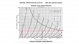
Attached is a CCS x 2 loadline for a 6N13s output tube. The design uses IXCP10M45 as a constant current source/plate load. And a TL783 as a constant current sink at the cathode. The 50ma load line seems about the best compromise for this tube
Attachments
Last edited:
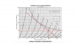
It's for the push pull amp I'm planning. I've attached what I think the load line from your amp might look like. I tried to analyse your circuit to guess at where your load line would fall. I'm working on a preliminary schematic for my amp.
Attachments
Last edited:
Attached is a CCS x 2 loadline for a 6N13s output tube. The design uses IXCP10M45 as a constant current source/plate load. And a TL783 as a constant current sink at the cathode.
Why a current source plate load and a current sink?
The tube is limited to 250 volts and only has a mu of 2. Another problem with the tube is the halves are notoriously mismatched. The constant current source acts as a plate load to block AC from grounding in the power supply and therefore maximize what little gain the tube has.
Another problem with the tube is the halves are notoriously mismatched.
I have not seen this.
I had a bias balance potentiometer in my amplifier but noticed that it was not needed.
When cathode voltage typically is around 120 V, some + 5 V has not much effect.
For me it is not clear what sort of combination you are building.
Does it really contain 6N13S triode, CCsink at the cathode, CCsources at the anodes and also output transformer ?
- Status
- This old topic is closed. If you want to reopen this topic, contact a moderator using the "Report Post" button.
- Home
- Amplifiers
- Tubes / Valves
- CCS Loadline