Hey Anyone,
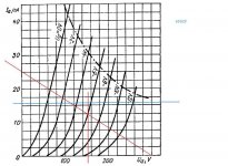
I've attached a loadline graph for 6N6P. I want to use an LT1086 as a CCS but I'm not sure how to plot the loadline? A normal loadline for 300 volts and 25 ma is shown in red. But if you use a CCS and the current is constant that won't work will it? To stay under the dissipation line I would be limited to 16ma, as drawn in blue. Is that correct? And when you use a CCS do you have a bias point? Or isn't there one?
Kevin
Attachments
Last edited:
And when you use a CCS do you have a bias point?
There is always a bias point. Looking at your vertical line, it intersects the horizontal line at a bias of about -5.5V. So that's one possible bias...
Thanks guys,
I guess my real question is how do I determine the voltage swing of the tube? I'm going to be using two 6N6Ps in a differential amplifier that will be fed into an inter-stage transformer to drive two 6L6. I know how to calculate a bias point for a cathode biased tube. And therefore I know where the voltage center will swing around. But with a CCS I do see how to do that?
I guess my real question is how do I determine the voltage swing of the tube? I'm going to be using two 6N6Ps in a differential amplifier that will be fed into an inter-stage transformer to drive two 6L6. I know how to calculate a bias point for a cathode biased tube. And therefore I know where the voltage center will swing around. But with a CCS I do see how to do that?
I know how to calculate a bias point for a cathode biased tube. And therefore I know where the voltage center will swing around. But with a CCS I do see how to do that?
Exactly the same way. The anode can swing from the 0V curve up to the HT voltage (actually a bit less than the HT, due to the drop out voltage of the CCS, but this should be pretty small).
But don't forget to include the effect of any following load, i.e., draw an AC load line.
So more or less such circuit (long tailed pair): The Valve Wizard
Last edited:
Oh, I thought you were trying to design a regular gain stage. If this is an LTP with CCS tail, then you don't draw a horizontal load line at all, since it is the tail current that is fixed, NOT the anode current(s).Yes between cathode and ground. I still don't understand the bias point here (dense). Maybe I should just use fixed bias and set it a -6 on the grid?
(It is a good idea, when starting a thread, to provide a bit more essential information about what you are trying to do.)
Last edited:
Kevin,
I think it is better to use cascoded BJT CCS instead of LT1086 - see p. 4 http://www.pastisch.se/faktiskt/diyAudio-CCS-beta3.pdf
I think it is better to use cascoded BJT CCS instead of LT1086 - see p. 4 http://www.pastisch.se/faktiskt/diyAudio-CCS-beta3.pdf
Hey Anyone,
I've attached a loadline graph for 6N6P.
A loadline is a loadline: period. If you use a CCS, then your loadline is effectively horizontal so long as the next stage load is Hi-Z, as it would be if the following stage was Class A with the usual 1M grid return. If the load is heavier, then your loadline will still tilt, and equal the smaller load. You can think of it as:
RL= INF || RL= RL (Keeping in mind that practical CCSs never achieve infinite Zo, but come close enough for all practical purposes when used within their frequency limitations.)
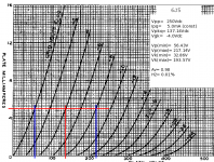
Here is an example (attached)
The DC loadline is horizontal. Pick a Q-point close to the center to maximize output swing. This falls at VGK= -4.0V. Having established that, the input swing is 8.0VP-P. Since the current is constant, you need to read off the Vpk from the characteristic.
Since this is a cathode follower, use the Vpk extremes to determine the cathode point voltages. This gives you the values for Vo and for Vi. Nothing would change were this a gain stage with the CCS connected between the plate and VPP other than it would have Av= 20 -- u-level voltage gain instead of the Av= 0.95 of the CF.
It's always the same loadline. When using a CCS, either in the cathode or plate, the Q-point bias sets the VPK as opposed to setting both IP and VPK. If the CCS is in the plate, the one thing you probably won't require is a cathode resistor bypass capacitor, as there is no AC current in the cathode that needs bypassing. It's also how the plate loaded CCS maximizes voltage gain: no degeneration in the cathode circuit.
I want to use an LT1086 as a CCS but I'm not sure how to plot the loadline?
You'd be better off using discrete BJTs to implement a cascode CCS rather than using an IC. The high frequency performance will be much improved.
Attachments
Hey All,
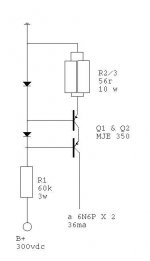
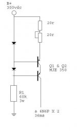
If anyone is still listening I've tried to figure out the cascoded BJT thing. Attached is what I've come up with. The CCS will be set for 36ma with a B+ of 300 volts. Since the current is high R2 and R3 will only have a combined resitance of 28 ohms. Playing it safe I went with two 56 ohm 10 watt resistors in parallel. If that doesn't work I can always vary one resistor to adjust it. the DIY CCS page doesn't really say much about the LED's do they have any special reqiurments? Does my math look right?
If anyone is still listening I've tried to figure out the cascoded BJT thing. Attached is what I've come up with. The CCS will be set for 36ma with a B+ of 300 volts. Since the current is high R2 and R3 will only have a combined resitance of 28 ohms. Playing it safe I went with two 56 ohm 10 watt resistors in parallel. If that doesn't work I can always vary one resistor to adjust it. the DIY CCS page doesn't really say much about the LED's do they have any special reqiurments? Does my math look right?
Attachments
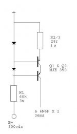
Okay, I've updated R2. But the explanation for the HV PNP CCS isn't clear to me. It says ...and the supply lead is grounded. Is the supply lead the lead labeled 'input'? And then the plates are connected to 'output'? Its logical but I want to make sure.
Attachments
Last edited:
So I have the B+ connection and the ground reversed? That makes more sense. The website from post 11 above says, Now in this case, the return is connected to the high voltage supply and the supply lead is grounded. So do you have to reverse the diodes?
I understand, I think, that each LED will drop a set voltage. which controls its transistor. The first, top pair, will drop a voltage and control the transistor at a low current. That transistor will be locked in tandem with the lower transistor. The only difference is that the lower transistor will be flowing much more current. Is that correct?
I understand, I think, that each LED will drop a set voltage. which controls its transistor. The first, top pair, will drop a voltage and control the transistor at a low current. That transistor will be locked in tandem with the lower transistor. The only difference is that the lower transistor will be flowing much more current. Is that correct?
yes, the LED sets the collector current, (LED voltage-0.65v)/28 ohms...
so that in case the LED drops 1.5 volts, then your CCS will source about 30mA...
the upper trannie will have lower collector voltage of the two in cascode,
about the same as LED voltage....
but collector currents are the same for the two...
so that in case the LED drops 1.5 volts, then your CCS will source about 30mA...
the upper trannie will have lower collector voltage of the two in cascode,
about the same as LED voltage....
but collector currents are the same for the two...
The website from post 11 above says, Now in this case, the return is connected to the high voltage supply and the supply lead is grounded.
Yes, that's indeed not terribly clear and the writer should be flogged. It would also have been nice if he showed a full schematic of the CCS in situ to prevent confusion. Eh, he was probably drunk at the time and busy beating his child.
Sy, I don't doubt you're ability to explain. I only doubt my ability to comprehend. But I think I have it now. My target for R2 and R3 is 28 ohms. So I'll use a 20 ohm resistor and a 20 ohm trimpot.
Another question? Is there any reason I can't put a Maida voltage regulator, set to 300 volts, ahead of the CCS?
Another question? Is there any reason I can't put a Maida voltage regulator, set to 300 volts, ahead of the CCS?
Attachments
- Status
- This old topic is closed. If you want to reopen this topic, contact a moderator using the "Report Post" button.
- Home
- Amplifiers
- Tubes / Valves
- CCS Loadline