Hello there,
Caught your message by pure chance. Not on here often.
Disclaimer: Not endorsing self-murder by electrocution from lethal DC voltages!!! (If you are uninformed of mortal danger of Valve(Tube) amps)
Been a while since I dared to go under the hood of a valve (toob) amp. Please be patient while I dust memory cobwebs...
As written above, it was the advice given by the HiFi shop technician that sold it to me. He was from Birmingham and had a very dry "Brummie" sense of humour, like Ozzy Osbourne of Black Sabbath.
He said somthing like "Yow don't want to touch thowse High Tension voltages or yow'lle be 6 feet across the rowm"...
The EL34 Power "toobs" are easy to bias, though dangerous, acheivable with a quality volt meter (that can stand high voltages without killing you).
I use a crimp connector to negative terminal and only poke the positive probe using one hand while other hand in pocket...
The Pre-Amp "toobs" are more difficult (and position of potentiometers more dangerous) requiring an oscilloscope and an insulated screwdriver.
He advised to set the potentiometers at 50% if without an oscilloscope. Said you won't be far-wrong (Better than being far-right, aparrotly).
Watched a youtube video by Mr Carlson's Lab on how to bias toobs with an oscilloscope. It's much less critical with toobs than transistors. Removing distortion from a sine wave. Toobs way more forgiving.
Thank you. I have a pair of Fluke 87V so I think I would hook up both at the same time. I also have those alligator clips that would save me from getting fried so I am currently waiting for some new fuse to get in before I try.
Thank guys for the help and I will report back with the result.
Thank guys for the help and I will report back with the result.
You have to observe the intended design current through the tube, among other things to ensure you are within the dissipation ratings of the tube. Earlier in the thread a plate current of 45-50 ma was mentioned as the specified value. With a HV supply of 480V as @iWozza ’s you better be below 52 ma, because then the plate is dissipating the maximum 25 watts.It's really just balancing the DC currents in the two output tubes of the pair,
but not adjusting it to a particular value.
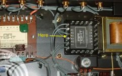
I do not understand the instructions to set bias because I don’t know what is the “copper Link Tap on Output Transformer” that has to be 3 volts below the anode voltage (pin 3).
Last edited:
I’ll appreciate an explanation of your advice. What makes it so hard to do the AC balance correctly.Don't touch the preamp adjustments.
Hi Francois,Careful! You have to observe the intended design current through the tube, among other things to ensure you are within the dissipation ratings of the tube. Earlier in the thread a plate current of 45-50 ma was mentioned as the specified value. With a HV supply of 480V as @iWozza ’s you better be below 52 ma, because then the plate is dissipating the maximum 25 watts.
I do not understand the instructions to set bias because I don’t know what is the “copper Link Tap on Output Transformer” that has to be 3 volts below the anode voltage (pin 3).
I don't understand the reasons behind my instructions.
The "Copper tab" was a bare wire link between taps on the output transformer.
Perhaps centre tap...? Looking at photos on here, think its between terminals 3 and 4 on the left side of the left output x-former from beneath.
Attachments
Thank you.
OK, I see, the physical copper tab appears to be the “Test point” on the schematic, that is the B+ end of each primary winding. So, the objective of the instructions is to equalize the DC voltages across each side of the primary winding. This implies that the resistance of each side of the winding is exactly equal. You may test that sometime (with the power off).
OK, I see, the physical copper tab appears to be the “Test point” on the schematic, that is the B+ end of each primary winding. So, the objective of the instructions is to equalize the DC voltages across each side of the primary winding. This implies that the resistance of each side of the winding is exactly equal. You may test that sometime (with the power off).
Finally got everything together and get ready to take a stab at it. Reading the comment so I just test the resistance. Both side on mine isn't equal (P1 is about 76ohm and P2 is about 66ohm).
Another thing is when I initially tried to put the general bias at 45V. The balance is about 3.8 VDC, is that ok? That is quite a bit higher than the 3V so I am a bit worry.
Another thing is when I initially tried to put the general bias at 45V. The balance is about 3.8 VDC, is that ok? That is quite a bit higher than the 3V so I am a bit worry.
Last edited:
For fear of misunderstanding and giving wrong advice, could you please explain exactly where you measured these values in reference to your schematic in post #36? Meanwhile, here is some food for thought.
I’m not an AirTight owner (could the AirTight owners speak up please) but an imbalance of 3-4 V in the bias voltage (measured between the cathode and control grid of each EL34?) of a push-pull pair of output tubes sounds too much (if it is a matched pair). If the tubes are unmatched then possibly, but not an ideal scenario.
The differences in resistance you measured in the two windings of the OT primary shows that it is not a good idea to use that unequal resistances to set the drop from the test point to the anode at an equal 3 V for both tubes. *Approximate plate current through one EL34 is I=V/R; 3.8/76=50 ma. The other side is 3.8/66=58 ma. (Remember 52 ma is the max to keep plate dissipation under 25W at 480V across the tube). That much imbalance in the push-pull will surely cause increased distortion in the OT. (*It is approximate due to the fact that this is a UL transformer that complicates the current calculation further, since screen current adds to the drop over the first 40% of the winding).
Unless AirTight is designed differently, the “normal objective” is to set the currents through each tube (and winding connected to it) to be equal. For matched tubes that will result in nearly equal grid bias, but will vary if the tubes are not matched.The key is to be able to measure the current through each tube accurately, and as mentioned earlier in this thread, that is usually done by inserting an accurate resistor (typically a 10 ohm, 1% resistor) between the tube cathode and circuit ground, and measuring the voltage across it to calculate the desired current (in this case the combined plate and screen current).
Alternatively, as mentioned in post #5 long ago, you could also use the actual resistance measurement of each winding on each side of the “Test point”, i.e. OT CT) and calculate what the voltage drop should be across the actual resistance at the desired current. These drops will be unequal due to the unequal winding resistances. Or you could look into the Octal bias adjustment meters mentioned in the same post. Finally, if you could find space for it in the AirTight, you could consider installing an automatic bias controller such as these: https://www.audioamp.eu/kategorie/modules-adaptive-bias-control/
Last edited:
After you have tamed the beast’s bias requirements, you could return to the AC balance issue, if it is an issue after all. I’m awaiting Rayma’s reply, about why he recommended to leave that in you AirTight alone (post #44). But if the amp doesn’t sound really good after the bias issue is solved I would encourage you to look into the AC balance adjustment. You have an oscilloscope and you can do it close enough, or at least improve it.
If needed I could provide link or two to AC Balance adjustment instructions and discussions. Some experts, like Jim McShane (HK Citation guru) believes that close is preferable to perfect in AC balance because of the harmonic profile, and some do it by ear, i.e. what sounds good to them. Point is that IMHO you will cause no harm and likely improve it by adjusting the AC balance a little at the time. Just mark the beginning setting so that you could return to it if needed.
If needed I could provide link or two to AC Balance adjustment instructions and discussions. Some experts, like Jim McShane (HK Citation guru) believes that close is preferable to perfect in AC balance because of the harmonic profile, and some do it by ear, i.e. what sounds good to them. Point is that IMHO you will cause no harm and likely improve it by adjusting the AC balance a little at the time. Just mark the beginning setting so that you could return to it if needed.
Last edited:
To start off, I am learning, so almost no experience or background knowledge (currently learning by myself). I can follow instruction that is it. I am also a bit hesitant to touch high-voltage lines so that is why I chose this method (3V instead of 480V). I just follow the instruction because it seems to be the only instruction specifically for the amp. I also read countless other and more try-and-true ways (measure and calculate voltage drop, I will maybe try it later once I am more comfortable with the amp).
For now, the resistance was measured between the Copper Tab and pin 3 of each of the tubes. Both sides are showing me identical measurements, so I am not sure. I used 2 DMM to measure both tubes at the same time. When I put the bias voltage at 45V (VR7) I get a value close to 4 VDC at pin 3 of both tubes after warming up (after balancing them out). It is 4VDC instead of 3VDC as the iWozza said so that is why I am a bit concerned. After balancing both sides, I leave it on for 30 minutes. Nothing seems to change, no red plating, no noise, no blowing fuse. I hooked up test speakers and simple input and get a clear sound.
Right now it is playing without any problem. It came with the original Air Tight set of tubes. I only swapped the output tubes (the AT tubes were red-plating but it may be because of the adjustment stuff) and left the rest alone. I will change the 5AR4 too even though they are working now because the Chinese tubes are noisy. The clinking sound they make when warming up is giving me anxiety and I have enough vintage 5AR4 to last me a while so.
I will try later, hunting for a scope right now. The 2 pots for it is weird. Right now they are at their lowest values or close to it (1.1 ohms and 4.7 ohms). I measured it, record the value and kinda fidget with it a bit but even a small change led to a large increase in resistance (magnitude of 100) so I stopped and return it to the original value (1.1 ohms and 4.8 ohms).After you have tamed the beast’s bias requirements, you could return to the AC balance issue, if it is an issue after all. I’m awaiting Rayma’s reply, about why he recommended to leave that in you AirTight alone (post #44). But if the amp doesn’t sound really good after the bias issue is solved I would encourage you to look into the AC balance adjustment. You have an oscilloscope and you can do it, or at least improve it.
If needed I could provide link or two to AC Balance adjustment instructions and discussions. Some experts, like Jim McShane (HK Citation guru) believes that close is preferable to perfect in AC balance because of the harmonic profile, and some do it by ear, i.e. what sounds good to them. Point is that IMHO you can cause no harm by adjusting the AC balance a little at the time. Just mark the beginning setting so that you could return to it if needed.
Could you remind me, why are you choosing to set the control grib bias at 45 V? Where do you measure this voltage? I would think 3 V is what you should adjust for, and let the bias be what is is to get you to 3 V. (As explained above, I don’t think this is the best way to adjust bias, but if you follow factory instruction 3 V is what you look for between the “Test point” and pin 3)
 You are touching 480V!!!! You are in fact measuring the difference between ~480V B+ and ~477V at pin 3 to get the 3V you measure. So, with due respect, if you did not understand that I would advise caution.
I am also a bit hesitant to touch high-voltage lines so that is why I chose this method (3V instead of 480V)
You are touching 480V!!!! You are in fact measuring the difference between ~480V B+ and ~477V at pin 3 to get the 3V you measure. So, with due respect, if you did not understand that I would advise caution.
Last edited:
I will try to adjust to get the 3V (bias voltage would be about 48 - 50V at VR7). I didn't know about the voltage on those 2 lines. I used alligator clips on both of the DMM so I didn't touch anything other than the pot with an insulated screwdriver. Glad to know that I just cheated death !!!!!!!!!!!!!!!! Like I said, I am learning, and at a very early stage (I work with electronics repair, mainly Apple devices), and can't really understand something like a complicated schematic unless I really sit down and take a long long time with it. Good thing I am an idiot who is deadly afraid of electricity so I will take all the precautions I can (which I don't normally worry about while working with logic boards, they have like 16V max).
I can't adjust both sides to 3V. When I tried that (using VR7 and pin 5 to ground at 51VDC) I got -3.3V on one channel and -2.7V on another channel. Is that right? The amp doesn't exhibit any weird behavior. The power transformer is running a bit hotter than I would like. I spent the last 3 hours listening to it without any problem but a bit concerned regarding the power trans temps. The 4 vintage tubes I put in aren't a matched quad, but the 2 tubes in each channel are closely matched. I also rotate the 5AR4, and put in a good vintage 5AR4. It is the same measurement. There is about -0.6 different between 2 channel when measured at pin 3 (red lead) to copper link.
Do you measure -3.3V at pin 3 of both V1 and V2, and -2.7V at both V3 and V4?
Since you apply the same negative voltage (via VR7) to bias both pairs of tubes, the pairs should be matched, i.e. you need a matched quad, not two pairs that behave differently. If you have a matched quad I expect the will bias equally at near where you have VR7 now. Since that is at the maximum negative of the range it appears that your negative bias voltage is limited. I suggest you check all the parts in the bias supply to see if they are still within specs and replace those that are not. If necessary you could replace the 1.5k resistor between the 80Vac tap and the diode with a 1.3k-1.4k to allow negative bias of -55 V or so.
It is hard to say what current capability you power transformer has, but unless it is too hot to touch it is probably OK. I would feel more confident in the assessment if the actual currents through the tubes are accurately measured and balanced (using the methods already discussed).
Last edited:
Every single component was checked to be in specs (equal and correct to their value or color codes). I have an ESR meter for the caps so I don't have to desolder them. The tubes I am using right now isn't a matched quad since I didnt wanna risk expensive tubes. I used 2 matched pairs (but not matched to each other. One pair was 42 / 42 over 30; the other was 32/32 over 30 on my TV7/U) so I will try to adjust bias using the more precise way then if it doesn't change I will get a matched quad.
Another thing is I can get the bias current to -55V, just not quite sure if I should. I don't fully understand bias, so I just follow the specs or value that I can find. Promise I'm learning everything as fast as I can and trying to catch up.
Another thing is I can get the bias current to -55V, just not quite sure if I should. I don't fully understand bias, so I just follow the specs or value that I can find. Promise I'm learning everything as fast as I can and trying to catch up.
- Home
- Amplifiers
- Tubes / Valves
- AirTight ATM-1 Schematic