Well, after over 40 years as a technician, I do know how to measure things. When I started, I had sometimes need to measure the HV to picturetubes, at 25 kV, and work with tube rectifiers and ballast tubes for the HV. And in one of the posts there was a description how to measure the bias by measure the voltage over the primary of the OT. Albeit the need to use the voltage range of the DVM, with high resistance in the instrument, that can be as dangerous if the instrument is a cheap one, and accidentaly put in a amp range. So use a Fluke or similar instrument, that is explosion proof. Better be safe than sorrow, OK?
Well, after over 40 years as a technician, I do know how to measure things. When I started, I had sometimes need to measure the HV to picturetubes, at 25 kV, and work with tube rectifiers and ballast tubes for the HV.
There are special HV probes made for that purpose.
Here's what the technician in the shop I bought my ATM-1 told me.
Be very careful etc.
ATM-1
Bias Balance of Power Valves in Pairs (Push/Pull)
1) Voltmeter Black -ve (DC voltage measurement) to copper Link Tap on Output Transformer and Red +ve to Pin 3 of Power Valve 1 then V2. Should be about 3 volts. Any imbalance to be adjusted with the potentiometer between valves.
2) Repeat for Valve 3 and V4 (P/P)
General Power Valve Bias
3) Put Voltmeter Negative to Amp Ground and Positive to Pin 5 of any valve to adjust general Bias. Should be -40v. Adjust Single Potentiometer in Power Supply section if needed.
Changing to new Power Valves
4) Before putting in a fresh set of Valves a precautionary General Bias setting of -45v can be dialled in to stop valves "running away”. Notably during Burn in Period.
5) Balance Bias as in Step 1).
6) Leave on and check an hour later, then 4 hours, then a day later and recalibrate. This will give valves a chance to burn in.
Biasing Preamp Section
7) Do not touch Preamp potentiometers as they need to be adjusted using a scope to check for distortion.
If a Preamp valve needs changing a rough guesstimate is about halfway on the potentiometer.
Any advice on Step 7?
I am quite reluctant to start soldering and poking around in this piece of japanese art.
Its a push-pull El34 amp with 12ax7 input and 12ua7 long tail pair phase splitter. Nothing original here. I would consider a CCS in the tail of the phase splitter...
")
It seems though that soldering will become inevitable at some point as my psu electrolytics (Nichicon Audio Professor) are drying out.
Fresh new electrolytics work wonders. Just don't go for "NOS' electrolytics. By-pass with a small, high quality film cap if you feel the need.
btw, here is a nicer looking schematic:
An externally hosted image should be here but it was not working when we last tested it.
wow, that filter choke is only 1.25H ? go figure...
Cheers for the clear schematic.
So it seems I was advised to do 2 things:
1) Set DC Balance VR 1, (2)
2) Set Idle Current VR 7 via the -40V bias???
I'm not an electronics engineer nor do I really know these things work.
However, I am pretty practical and a tec of sorts and can solder.
I guess I was advised against altering the VR 3, (4) AC Balance as he mentioned using a scope for distortion.
I have 2 questions;
1) Can I adjust AC Balance with a voltmeter on AC or is that not right?
2) How easy is the CSS mod in the tail of the phase splitter and what is that all about? Had a quick google about it.
Thanks
If you have not touched VR 3 (4) then its probably best to leave it as is. I assume the technician in the shop has gone over the unit, so it should have been set to a reasonable position.
If you have no experience and don't understand circuits well, then don't bother with the CCS mod.
I personally don't like the idea of adjusting bias of the EL34's by measuring voltage drop across the primary windings of the output transformer. These are quite high DC voltages that are LETHAL. I hope your multimeter is a good quality one as noted already in previous posts. I hope you take the time to read posts on how to safely do this...
The old school method is to permanently insert some small value cathode resistor for each EL34 (i.e 10 ohms metal film, half watt or higher) so you can measure voltage drop and calculate individual current of each EL34 at a safe voltage. I would consider this modification, although some purists might find some reason or other against it. This I leave up to you.
Keep in mind that adjusting VR1(2) will move the current of one EL34 UP and the other EL34 DOWN simultaneously. It is like moving the fulcrum on a teeter-totter (or set of scales). So you need to measure back and forth to find the point where they match. This is not so nice to be doing over the high voltages of the output transformer primary windings.
Now here is perhaps something useful for you to consider. If you have a NEW matched QUAD of EL34's, VR1 and VR2 should (theoretically) be set right in the middle. That means 5k Ohm on each side of the wiper.
If in doubt, I would suggest you take it to the tech where you bought it and pay them to make appropriate adjustments. If he is a good tech, he will probably not let you watch him do this as it might make him nervous which can increase chance of mishaps..
Last edited:
It came calibrated with East German Siemens valves.
I found some sanely priced, used Blackburn Mullards to see if there was an improvement so rang up the shop asking what to do.
My voltmeter must be OK because it hasn't blown up. I make a point clipping one terminal and not putting both hands in the amp.
I know a bunch of electronics people who scared me into paying extra attention and thinking twice when dealing with mains. I know Big DC is the killer.
Would the CSS mod affect sonics or is it just for the convenience of Biasing?
Hi Smokingamp
These adapters may work well with individual tubes/valves, but for this amlifier, when you adjust the bias UP on one, it goes DOWN on the other.
So indeed it is not a bias adjustment, but a balance adjustment.
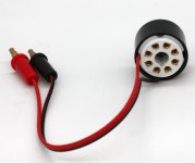
I suppose if you had two of these it could be used. I had one of these given to me from a friend. I never used it, so don’t know what the leads are even.
If one is the plate, then the ‘careful with high voltages’ rule is still there.
These adapters may work well with individual tubes/valves, but for this amlifier, when you adjust the bias UP on one, it goes DOWN on the other.
So indeed it is not a bias adjustment, but a balance adjustment.
I suppose if you had two of these it could be used. I had one of these given to me from a friend. I never used it, so don’t know what the leads are even.
If one is the plate, then the ‘careful with high voltages’ rule is still there.
Last edited:
Btw, assuming your DVM is good quality with decent rated leads, this is what I would do:
Set the ‘balance’ VR in the middle (probably already close to this anyway, but I would still check it).
Put in your new ‘matched’ el34’s.
Clip your negative lead of the DVM to ground.
Turn on and check (adjust) ‘negative bias’ VR to correct to reference value as needed.
Using your right hand, use the positive lead to check plate voltages for each EL34.
Adjust the ‘balance’ VR as needed to get similar plate voltages for the el34 pair
Check individual grid bias voltages. They should not be too different, or else your ‘new matched’ el34’s are not paired up well....
If needed, compare grid bias and plate voltage values between channels. It is better to have two ‘weaker’ el34’s paired up, and two ‘stronger’ el34’s paired up.
Last edited:
The octal tube socket current test/adapters are only like $13 on Ebay. They break the cathode connection and bring those out as leads for a current meter. (black wire from plug end pin 8 and red wire from socket end pin 8, connect black to - on meter, connect red to + on meter) There is no HV on them. Just use two of them and two meters (mA current setting) for the balancing/bias type amplifier. Way safer than messing with HV B+.
Could probably build a set of them for $10. An octal plug and an octal socket for each. Wire all pins directly thru except pin 8 which comes out as the two test leads. Black wire from the plug pin 8 and red wire from the socket pin 8. Every service shop should have these. So simple to use on any amplifier (with 6L6, EL34, KT88 etc octal basing).
There are even adapter current test models on Ebay for TV Sweep tube basing too (Compactron, pin 2 cathode). Also 9 pin Noval ones for EL84/6BQ5 (pin 3 cathode).
Last edited:
The octal tube socket current test/adapters are only like $13 on Ebay.
Does sound convenient and safer, maybe more so for other amps (?) but you still have to turn the ATM-1 upside down, take the base off to put a screw driver in and adjust the pots. That could easily slip and short something if you were not careful. Unless its plastic of course...
Sounds like they made the ATM-1 S a lot safer by putting the pots outside and including a biasing meter.
I would like to learn how to do the Preamp Part (AC Balance). I need a scope to do a few other things so will get one at some point.
Does not matter too much, the current capability, inductance and turns ratio are more important. If you have a couple of output taps you can select the one that works best.does anyone know how much kohm is the output transformer in the ATM-1
OTOH I only glanced through the thread and IIRC there is noted a difference between the d.c. resistances of one plate winding versus the other. I had the same issue with my Hashimoto. This means that the transformer is not bifilar wound and only the bifilar wound transformers are regarded as belonging to the best. What effect this has in the end on the sound quality I do not know.
Last edited:
Revised ATM-1 Schematic
Had a go at redrawing the schematic in Inkscape due to the original being a bit lo-fi.
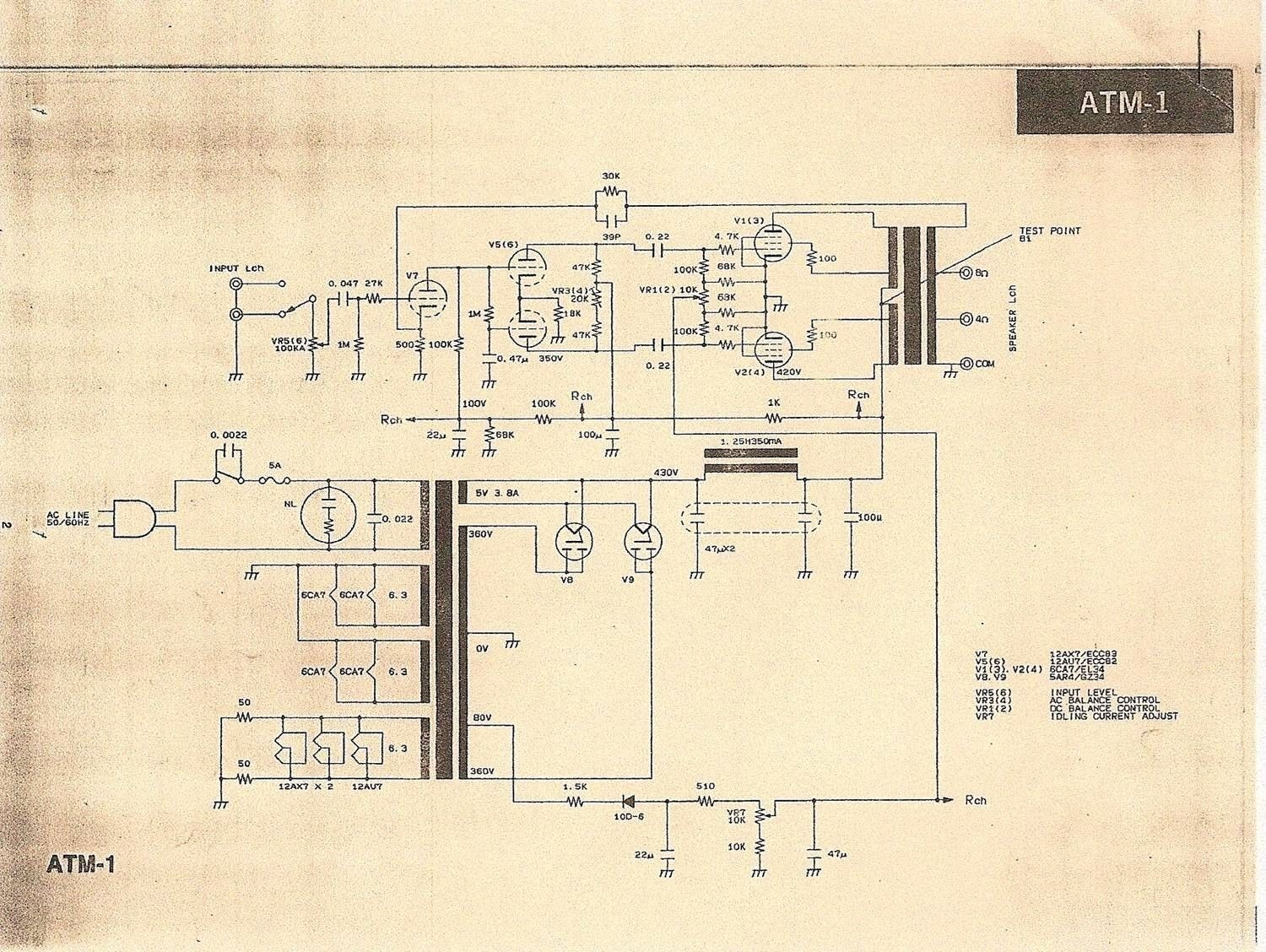
I had a problem when 2 "NOS" Russian GZ34 started arcing then blew the fuse after about 2 weeks use. Google found many similar happenings on guitar amp forums.
I feared there was something wrong with my amp and mentioned it to Jacmusic. He informed me the Rectifiers were rigged up wrong and that arcing happens mostly with bad circuit design.
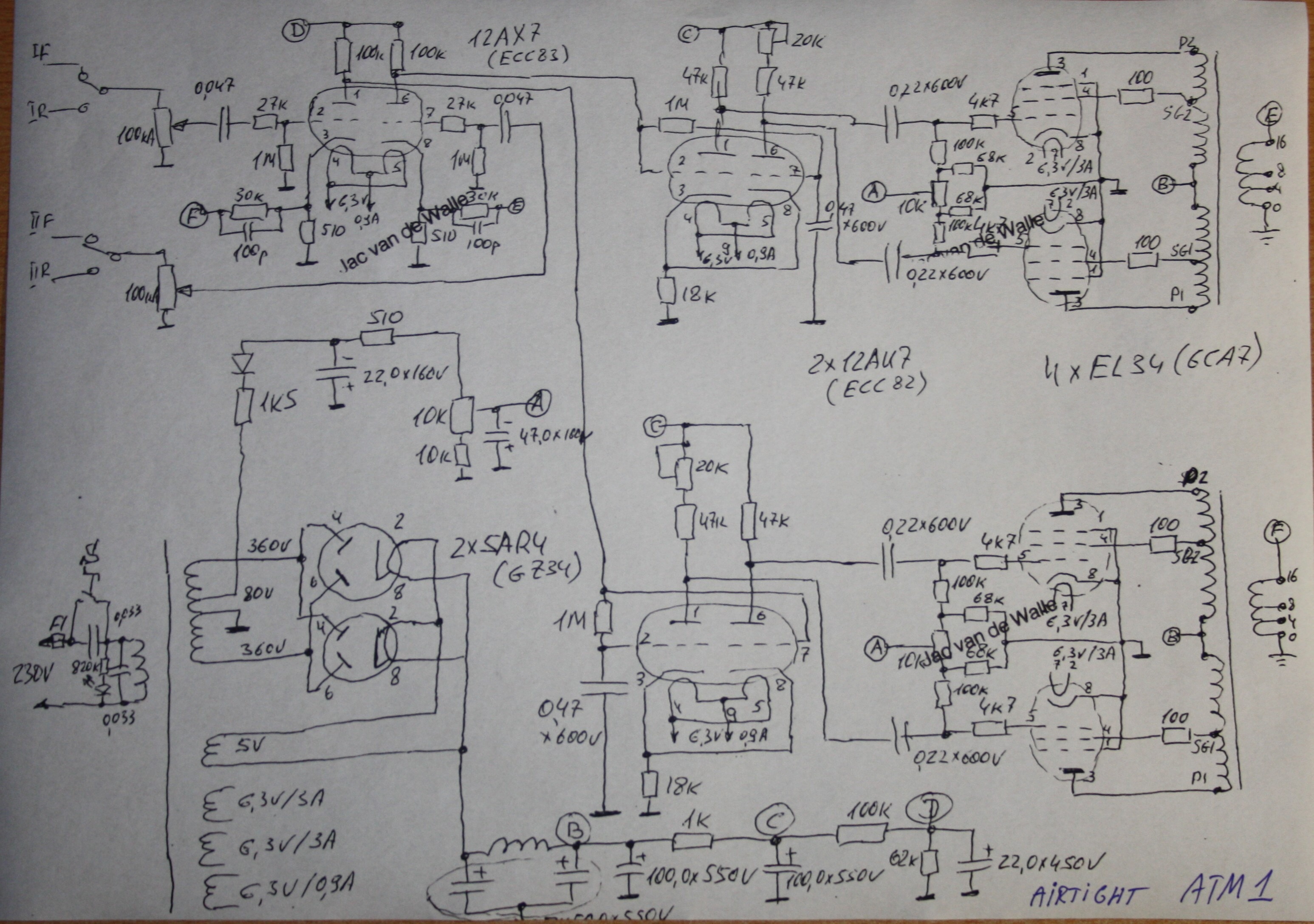
Turns out my rectifiers are actually wired up right but the schematic is drawn wrong!
They are drawn the right way on that hand drawn schematic below.
However, my HV voltages measured quite different.
Heaters good at 6.3V and 5V so the power transformer must be 240V (badly scrawled in biro).
HV Transformer is 370V instead of 360V
HV rectified is 480V instead of the 430V on schematic.
I also discovered my Output Transformers were wired for 8-16Ω instead of the 8-4Ω taps.
My feeling was although the amp had an insightful mid range it lacked bass weight and could be a bit peircy on the top end. I conjected it maybe for tiny Tokyo aparments that didn't want to blast neighbours with heavy bass.
Little did I know my speakers were connected to 16Ω all along....
Soldering iron out - Moved speaker outs to the correct taps...
Put the old USA Golden Lion rectifiers in and Bingo Wins!!
1) The amp sounds Fat, Gorgeous and no longer Piercy
2) No Arcing whatsoever on the old rectifiers....
So the ATM-1 adventure is born again
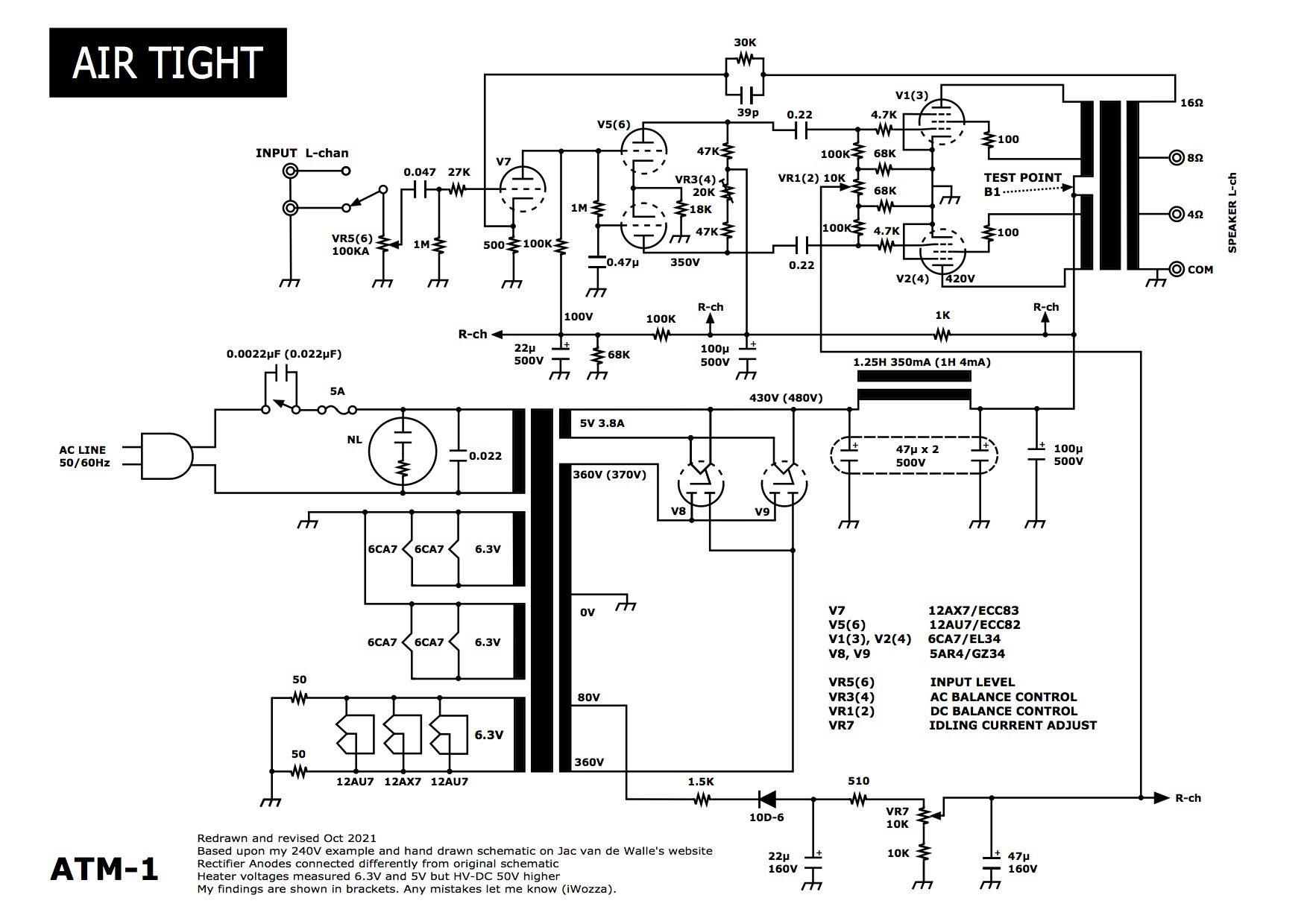
For them that like to zoom in here's the PDF...
ATM-1 Redrawn and Revised 2.pdf | PDF Host
The URL has changed for the original schematic on 4tubes.com
Had a go at redrawing the schematic in Inkscape due to the original being a bit lo-fi.
I had a problem when 2 "NOS" Russian GZ34 started arcing then blew the fuse after about 2 weeks use. Google found many similar happenings on guitar amp forums.
I feared there was something wrong with my amp and mentioned it to Jacmusic. He informed me the Rectifiers were rigged up wrong and that arcing happens mostly with bad circuit design.
Turns out my rectifiers are actually wired up right but the schematic is drawn wrong!
They are drawn the right way on that hand drawn schematic below.
However, my HV voltages measured quite different.
Heaters good at 6.3V and 5V so the power transformer must be 240V (badly scrawled in biro).
HV Transformer is 370V instead of 360V
HV rectified is 480V instead of the 430V on schematic.
I also discovered my Output Transformers were wired for 8-16Ω instead of the 8-4Ω taps.
My feeling was although the amp had an insightful mid range it lacked bass weight and could be a bit peircy on the top end. I conjected it maybe for tiny Tokyo aparments that didn't want to blast neighbours with heavy bass
.Little did I know my speakers were connected to 16Ω all along....
Soldering iron out - Moved speaker outs to the correct taps...
Put the old USA Golden Lion rectifiers in and Bingo Wins!!
1) The amp sounds Fat, Gorgeous and no longer Piercy
2) No Arcing whatsoever on the old rectifiers....
So the ATM-1 adventure is born again
For them that like to zoom in here's the PDF...
ATM-1 Redrawn and Revised 2.pdf | PDF Host
The URL has changed for the original schematic on 4tubes.com
Last edited:
Help Biasing Preamp section
Can anyone help me learn how to tune the AC Balance Control on the Preamp section, please?
I was told by the shop engineer I needed to use a scope but didn't have one at the time. He taught be how to Balance the DC on the power valves using a voltmeter and how to set the Idle Current. Risky but easy.
Now I have a soundcard scope which I plug into the Mic input of a PC and run Scope software. It's no good for voltage values but is good for showing wave shapes so you can spot distortions.
Before Health and Saftey tell me to buy safety sockets I shall remind what someone else said ealier on this thread. You have to turn the amp upside down and open it up to adjust the Potentiometers. The Power Valve Pots have 480V on the metal bit you turn so it's risky even with safety sockets.
Also, you can't bias individual valves, only balance pairs.
Ta
Is this the process????Here's what the technician in the shop I bought my ATM-1 told me.
Be very careful etc.
ATM-1
Bias Balance of Power Valves in Pairs (Push/Pull)
1) Voltmeter Black -ve (DC voltage measurement) to copper Link Tap on Output Transformer and Red +ve to Pin 3 of Power Valve 1 then V2. Should be about 3 volts. Any imbalance to be adjusted with the potentiometer between valves.
2) Repeat for Valve 3 and V4 (P/P)
General Power Valve Bias
3) Put Voltmeter Negative to Amp Ground and Positive to Pin 5 of any valve to adjust general Bias. Should be -40v. Adjust Single Potentiometer in Power Supply section if needed.
Changing to new Power Valves
4) Before putting in a fresh set of Valves a precautionary General Bias setting of -45v can be dialled in to stop valves "running away”. Notably during Burn in Period.
5) Balance Bias as in Step 1).
6) Leave on and check an hour later, then 4 hours, then a day later and recalibrate. This will give valves a chance to burn in.
Biasing Preamp Section
7) Do not touch Preamp potentiometers as they need to be adjusted using a scope to check for distortion.
If a Preamp valve needs changing a rough guesstimate is about halfway on the potentiometer.
Any advice on Step 7?
- Home
- Amplifiers
- Tubes / Valves
- AirTight ATM-1 Schematic