If you’re on Linux then the following commands my be of interest:
If your Linux has the rename command install great, if not then install - here I’m using Ubuntu:
Next once the files are put into the right spot you can rename the .inc files to .sub in one handy command:
Then to replace the ^ with ** in all the files for LTspice, use the following command:
If your Linux has the rename command install great, if not then install - here I’m using Ubuntu:
Code:
sudo apt install renameNext once the files are put into the right spot you can rename the .inc files to .sub in one handy command:
Code:
rename ‘S/\.inc$/\.sub/‘ *.incThen to replace the ^ with ** in all the files for LTspice, use the following command:
Code:
find . -name \*.sub -exec sed -i “s/\^/**/g” {} \;7199Thanks, Ale. Maybe someone can produce models from the published curves:
https://frank.pocnet.net/sheets/168/7/7199.pdf
From Wikipedia, the free encyclopedia
Jump to navigation Jump to search The 7199 is a vacuum tube, combining a pentode and triode.[1] Typically, the pentode was used for the input stage, and the triode as a phase inverter.[2] The tube was used in a number of American guitar amplifiers; the Gibson Guitar Corporation, for instance, used the 7199 in 1961's Falcon for the reverb circuit.[3] Ampeg also used the 7199 extensively.[1] Notable is the Dynaco ST-70 stereo amplifier introduced in 1959 which used a 7199 tube in the driver section of each channel. Over the next decade more than 350,000 of these amplifiers were produced. American 7199 production ended sometime in the 1980s while the Soviet tube company Sovtek produced one until roughly 2007. As a result the tube is becoming increasingly scarce. Another tube of the same type found in far more plentiful supply is the 6U8A, which is electrically identical, but with a different pinout configuration. The 6U8A can be substituted for a 7199 using a readily available adapter, or by making a slight modification to the wiring of its tube socket.
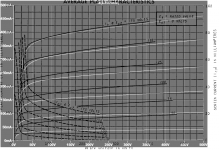
Here are the model for 7199 pentode and triode section:
Triode
Code:
 * [URL="http://www.dmitrynizh.com/tubeparams_image.htm"]www.dmitrynizh.com/tubeparams_image.htm[/URL]
* Plate Curves image file: 7199-t.png
* Data source link:
*----------------------------------------------------------------------------------
.SUBCKT 7199_T 1 2 3 ; Plate Grid Cathode
+ PARAMS: CCG=2.3P  CGP=2P CCP=0.3P
+ MU=38.09 KG1=166.22 KP=68.02 KVB=1832.64 VCT=-1.724 EX=0.8601
+ VGOFF=-0.61 IGA=1.751E-4 IGB=0.0603 IGC=12.96 IGEX=1.431
* Vp_MAX=280 Ip_MAX=22.5 Vg_step=2 Vg_start=0 Vg_count=9
* Rp=4000 Vg_ac=55 P_max=2.4 Vg_qui=-48 Vp_qui=300
* X_MIN=65 Y_MIN=8 X_SIZE=775 Y_SIZE=630 FSZ_X=1296 FSZ_Y=736 XYGrid=true
* showLoadLine=n showIp=y isDHT=n isPP=n isAsymPP=n showDissipLimit=y
* showIg1=y gridLevel2=y isInputSnapped=n
* XYProjections=n harmonicPlot=n dissipPlot=n
*----------------------------------------------------------------------------------
E1 7 0 VALUE={V(1,3)/KP*LOG(1+EXP(KP*(1/MU+(VCT+V(2,3))/SQRT(KVB+V(1,3)*V(1,3)))))}
RE1 7 0 1G  ; TO AVOID FLOATING NODES
G1 1 3 VALUE={(PWR(V(7),EX)+PWRS(V(7),EX))/KG1}
RCP 1 3 1G   ; TO AVOID FLOATING NODES
C1 2 3 {CCG} ; CATHODE-GRID
C2 2 1 {CGP} ; GRID=PLATE
C3 1 3 {CCP} ; CATHODE-PLATE
RE2 2 0 1G
EGC 8 0 VALUE={V(2,3)-VGOFF} ; POSITIVE GRID THRESHOLD
GG 2 3 VALUE={(IGA+IGB/(IGC+V(1,3)))*(MU/KG1)*(PWR(V(8),IGEX)+PWRS(V(8),IGEX))}
.ENDS
*$
Code:
* [URL="http://www.dmitrynizh.com/tubeparams_image.htm"]www.dmitrynizh.com/tubeparams_image.htm[/URL]
* Plate Curves image file: 7199-p.png
* Data source link: <plate curves URL>
*----------------------------------------------------------------------------------
.SUBCKT 7199_P P G2 G K ; LTSpice tetrode.asy pinout
* .SUBCKT 7199_P P G K G2 ; Koren Pentode Pspice pinout
+ PARAMS: MU=44.4 KG1=544.52 KP=108.69 KVB=1078.62 VCT=-0.4676 EX=1.284 KG2=741.65 KNEE=327.17 KVC=2.32
+ KLAM=9.971E-8 KLAMG=1.551E-4  KD=4.862 KC=1.105E-9 KR1=0.3576 KR2=0.02688 KVBG=0.01121 KB1=0.544 KB2=6.42 KB3=2.46 KB4=0.1404 KVBGI=0.01115 KNK=0.1675 KNG=0.05509 KNPL=0.02375 KNSL=0.0739 KNPR=0.2612 KNSR=14.72
+ CCG=3P CGP=1.4P CCP=1.9P VGOFF=-1.5 IGA=0.002687 IGB=0.05343 IGC=13.36 IGEX=1.764
* Vp_MAX=300 Ip_MAX=25 Vg_step=1 Vg_start=0 Vg_count=11
* X_MIN=49 Y_MIN=10 X_SIZE=780 Y_SIZE=657 FSZ_X=1287 FSZ_Y=723 XYGrid=false
* Rp=1400 Vg_ac=20 P_max=3 Vg_qui=-5 Vp_qui=300
* showLoadLine=n showIp=y isDHP=n isPP=n isAsymPP=n isUL=n showDissipLimit=y
* showIg1=y isInputSnapped=y addLocalNFB=n
* XYProjections=n harmonicPlot=y dissipPlot=n
* UL=0.43 EG2=130 gridLevel2=y addKink=y isTanhKnee=n advSigmoid=y
*----------------------------------------------------------------------------------
RE1  7 0  1G    ; DUMMY SO NODE 7 HAS 2 CONNECTIONS
E1   7 0  VALUE=  ; E1 BREAKS UP LONG EQUATION FOR G1.
+{V(G2,K)/KP*LOG(1+EXP((1/MU+(VCT+V(G,K))/SQRT(KVB+V(G2,K)*V(G2,K)))*KP))}
RE2  6 0  1G    ; DUMMY SO NODE 6 HAS 2 CONNECTIONS
E2  6 0  VALUE={(PWR(V(7),EX)+PWRS(V(7),EX))} ; Kg1 times KIT current
E4   8 0  VALUE={V(P,K)/KNEE/(KVBGI+V(6)*KVBG)}
E5  81 0  VALUE={PWR(V(8),KB1)}
E6  82 0  VALUE={PWR(V(8),KB2)}
E7  83 0  VALUE={PWR(V(8),KB3)}
E8   9 0  VALUE={PWR(1-EXP(-V(81)*(KC+KR1*V(82))/(KD+KR2*V(83))),KB4)*1.5708}
RE4  8 0  1
RE5 81 0  1
RE6 82 0  1
RE7 83 0  1
RE8  9 0  1
RE21 21 0 1
E21  21 0 VALUE={V(6)/KG1*V(9)} ; Ip with knee but no slope and no kink
RE22 22 0 1 ; E22: kink curr deviation for plate
E22  22 0 VALUE={V(21)*LIMIT(KNK-V(G,K)*KNG,0,0.3)*(-ATAN((V(P,K)-KNPL)/KNSL)+ATAN((V(P,K)-KNPR)/KNSR))}
G1   P K  VALUE={V(21)*(1+KLAMG*V(P,K))+KLAM*V(P,K) + V(22)}
G2   G2 K  VALUE={V(6)/KG2*(KVC-V(9))/(1+KLAMG*V(P,K)) - V(22)}
RCP  P K  1G     ; FOR CONVERGENCE
C1   K G  {CCG}  ; CATHODE-GRID 1
C2   G P  {CGP}  ; GRID 1-PLATE
C3   K P  {CCP}  ; CATHODE-PLATE
RE23 G 0 1G
GG G K VALUE={(IGA+IGB/(IGC+V(P,K)))*(MU/KG1)*
+(PWR(V(G,K)-VGOFF,IGEX)+PWRS(V(G,K)-VGOFF,IGEX))}
.ENDS
*$
Attachments
There's this:
6GE5 Pentode Model – Bartola(R) Valves
According to this,
"6JN6 is equivalent to 6GE5, 6FW5, 6DQ6B and 6GV5. So I would check to see if something is available for one of them."
If that's true, then these LTspice Ayumi models should work...
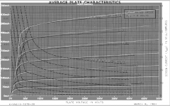
6DQ6 Pentode:
Code:* * Generic pentode model: 6DQ6 * Copyright 2003--2008 by Ayumi Nakabayashi, All rights reserved. * Version 3.10, Generated on Sat Mar 8 22:39:50 2008 * Plate * | Screen Grid * | | Control Grid * | | | Cathode * | | | | .SUBCKT 6DQ6 A G2 G1 K BGG GG 0 V=V(G1,K)+-1 BM1 M1 0 V=(0.17812317*(URAMP(V(G2,K))+1e-10))**-1.6443126 BM2 M2 0 V=(0.47705181*(URAMP(V(GG)+URAMP(V(G2,K))/2.9358797)))**3.1443126 BP P 0 V=0.0034562529*(URAMP(V(GG)+URAMP(V(G2,K))/6.1542156))**1.5 BIK IK 0 V=U(V(GG))*V(P)+(1-U(V(GG)))*0.0040197798*V(M1)*V(M2) BIG IG 0 V=0.0017281264*URAMP(V(G1,K))**1.5*(URAMP(V(G1,K))/(URAMP(V(A,K))+URAMP(V(G1,K)))*1.2+0.4) BIK2 IK2 0 V=V(IK,IG)*(1-0.4*(EXP(-URAMP(V(A,K))/URAMP(V(G2,K))*15)-EXP(-15))) BIG2T IG2T 0 V=V(IK2)*(0.980449351*(1-URAMP(V(A,K))/(URAMP(V(A,K))+10))**1.5+0.019550649) BIK3 IK3 0 V=V(IK2)*(URAMP(V(A,K))+2287.5)/(URAMP(V(G2,K))+2287.5) BIK4 IK4 0 V=V(IK3)-URAMP(V(IK3)-(0.0026038839*(URAMP(V(A,K))+URAMP(URAMP(V(G2,K))-URAMP(V(A,K))))**1.5)) BIP IP 0 V=URAMP(V(IK4,IG2T)-URAMP(V(IK4,IG2T)-(0.0026038839*URAMP(V(A,K))**1.5))) BIAK A K I=V(IP)+1e-10*V(A,K) BIG2 G2 K I=URAMP(V(IK4,IP)) BIGK G1 K I=V(IG) * CAPS CGA G1 A 0.5p CGK G1 K 8.7p C12 G1 G2 5.8p CAK A K 6.5p .ENDS
6DQ6 Triode:
Code:* * Generic triode model: 6DQ6T * Copyright 2003--2008 by Ayumi Nakabayashi, All rights reserved. * Version 3.10, Generated on Sat Mar 8 22:39:50 2008 * Plate * | Grid * | | Cathode * | | | .SUBCKT 6DQ6T A G K BGG GG 0 V=V(G,K)+-1 BM1 M1 0 V=(0.17812317*(URAMP(V(A,K))+1e-10))**-1.6443126 BM2 M2 0 V=(0.47705181*(URAMP(V(GG)+URAMP(V(A,K))/2.9358797)+1e-10))**3.1443126 BP P 0 V=0.0034562529*(URAMP(V(GG)+URAMP(V(A,K))/6.1542156)+1e-10)**1.5 BIK IK 0 V=U(V(GG))*V(P)+(1-U(V(GG)))*0.0040197798*V(M1)*V(M2) BIG IG 0 V=0.0017281264*URAMP(V(G,K))**1.5*(URAMP(V(G,K))/(URAMP(V(A,K))+URAMP(V(G,K)))*1.2+0.4) BIAK A K I=URAMP(V(IK,IG)-URAMP(V(IK,IG)-(0.0026038839*URAMP(V(A,K))**1.5)))+1e-10*V(A,K) BIGK G K I=V(IG) * CAPS CGA G A 6.3p CGK G K 8.7p CAK A K 6.5p .ENDS
I run 6DQ6 model for screen-drive with zero grid voltage,
and the results are much different from data sheet or experiments.
Is there any tools or methods I can modify the parameter?
I can build a model of the tube you used if you want. Ayumi model does not matched GE or Tung Sol curves. It may become close when the screen voltage is adjusted depend on the tubes you use. E.g if the Vg2 difference is -15V (150v-135v) then you reduce screen drive by 15v. This is fudge factor for different Vg2 curve, I think. You'll need the IV curve for Vg2 as well, see if can plot it.
Last edited:
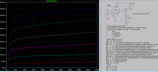
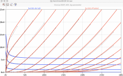
Here is comparison of IV curve for Vg2 of Ayumi 6dq6 model and Ge curve after Vg2 has been reduced by 15V, it's very close at top 175v and bottom 50v somewhat loose in between.
Attachments
Last edited:
I made 2 mistakes, one is the scaling. the previous curve is Tung Sol which can't compensated even with screen voltage adjusted. But the Ayumi model actually matched quite well with GE curve without any adjustment, except the tilt a little to the left. If you want other models please request.
Attachments
Hi all
God news for those who like cheap russian tubes
Here my model for the 6N3P.
My "golden Sample" is out of 5 tubes, each burned-in for 100 hours - so my model claimes to be pretty close to reality!
all the best, Adrian
God news for those who like cheap russian tubes
Here my model for the 6N3P.
My "golden Sample" is out of 5 tubes, each burned-in for 100 hours - so my model claimes to be pretty close to reality!
all the best, Adrian
Code:
*6N3P LTspice model based on the generic triode model from Adrian Immler, version i4
*A version log is at the end of this file
*100h BurnIn of 10 Vinniza factory tubes, sample selection and measurements done in Oct. 2020
*Params fitted to the measured values by Adrian Immler, Nov. 2020
*The high fit quality is presented at adrianimmler.simplesite.com
*History's best of tube decribing art (plus some new ideas) is merged to this new approach.
*@ neg. Vg, Ia accuracy is similar to Koren or Ayumi models.
*@ small neg. Vg, the "Anlauf" current is considered.
*@ pos. Vg, Ig and Ia accuracy is on a unrivaled level.
*This offers new simulation possibilities like bias point setting with MOhm grid resistor,
*Audion radio circuits, low voltage amps, guitar distortion stages or pulsed stages.
* anode (plate)
* | grid
* | | cathode
* | | |
.subckt 6N3P.VIi4 A G K
.params
*Parameters for the space charge current @ Vg <= 0
+ mu = 47.5 ;Determines the voltage gain @ constant Ia
+ rad = 5k3 ;Differential anode resistance, set @ Iad and Vg=0V
+ Vct = 0.25 ;Offsets the Ia-traces on the Va axis. Electrode material's contact potential
+ kp = 135 ;Mimics the island effect
+ xs = 1.35 ;Determines the curve of the Ia traces. Typically between 1.2 and 1.8
*
*Parameters for assigning the space charge current to Ia and Ig @ Vg > 0
+ kB = 0.7 ;Describes how fast Ia drops to zero when Va approaches zero.
+ radl = 250 ;Differential resistance for the Ia emission limit @ very small Va and Vg > 0
+ tsh = 16 ;Ia transmission sharpness from 1th to 2nd Ia area. Keep between 3 and 20. Start with 20.
+ xl = 1.3 ;Exponent for the emission limit
*
*Parameters of the grid-cathode vacuum diode
+ kvdg = 85 ;virtual vacuumdiode. Causes an Ia reduction @ Ig > 0.
+ kg = 970 ;Inverse scaling factor for the Va independent part of Ig (caution - interacts with xg!)
+ Vctg = 0 ;Offsets the log Ig-traces on the Vg axis. Electrode material's contact potential
+ xg = 1.5 ;Determines the curve of the Ig slope versus (positive) Vg and Va >> 0
+ VT = 0.11 ;Log(Ig) slope @ Vg<0. VT=k/q*Tk (cathodes absolute temp, typically 1150K)
+ kVT=115m ;Va dependant koeff. of VT
+ Vft2 = 0 gft2 = 9 ;finetunes the gridcurrent @ low Va and Vg near zero
*
*Parameters for the caps
+ cag = 1p6 ;From datasheet
+ cak = 1p4 ;From datasheet
+ cgk = 2p8 ;From datasheet
*
*special purpose parameters
+ os = 1 ;Overall scaling factor, if a user wishes to simulate manufacturing tolerances
*
*Calculated parameters
+ Iad = 100/rad ;Ia where the anode a.c. resistance is set according to rad.
+ ks = pow(mu/(rad*xs*Iad**(1-1/xs)),-xs) ;Reduces the unwished xs influence to the Ia slope
+ ksnom = pow(mu/(rad*1.5*Iad**(1-1/1.5)),-1.5) ;Sub-equation for calculating Vg0
+ Vg0 = Vct + (Iad*ks)**(1/xs) - (Iad*ksnom)**(2/3) ;Reduces the xs influence to Vct.
+ kl = pow(1/(radl*xl*Ild**(1-1/xl)),-xl) ;Reduces the xl influence to the Ia slope @ small Va
+ Ild = sqrt(radl)*1m ;Current where the Il a.c. resistance is set according to radl.
*
*Space charge current model
Bggi GGi 0 V=v(Gi,K)+Vg0 ;Effective internal grid voltage.
Bahc Ahc 0 V=uramp(v(A,K)) ;Anode voltage, hard cut to zero @ neg. value
Bst St 0 V=uramp(max(v(GGi)+v(A,K)/(mu), v(A,K)/kp*ln(1+exp(kp*(1/mu+v(GGi)/(1+v(Ahc)))))));Steering volt.
Bs Ai K I=os/ks*pow(v(St),xs) ;Langmuir-Childs law for the space charge current Is
*
*Anode current limit @ small Va
.func smin(z,y,k) {pow(pow(z+1f, -k)+pow(y+1f, -k), -1/k)} ;Min-function with smooth trans.
Ra A Ai 1
Bgl Gi A I=min(i(Ra)-smin(1/kl*pow(v(Ahc),xl),i(Ra),tsh),i(Bgvd)*exp(4*v(G,K))) ;Ia emission limit
*
*Grid model
Bvdg G Gi I=1/kvdg*pwrs(v(G,Gi),1.5) ;Reduces the internal effective grid voltage when Ig rises
Rgip G Gi 1G ;avoids some warnings
Cvdg G Gi 0p1;this small cap improves convergence
.func fVT() {VT*exp(-kVT*sqrt(v(A,K)))}
.func Ivd(Vvd, kvd, xvd, VTvd) {if(Vvd < 3, 1/kvd*pow(VTvd*xvd*ln(1+exp(Vvd/VTvd/xvd)),xvd), 1/kvd*pow(Vvd, xvd))} ;Vacuum diode function
Bgvd Gi K I=Ivd(v(G,K) + Vctg, kg/os, xg, fVT())
.func ft2() {gft2*(1-tanh(3*(v(G,K)+Vft2)))} ;Finetuning-func. improves ig-fit @ Vg near -0.5V, low Va.
Bgr Gi Ai I=ivd(v(GGi),ks/os, xs, 1.1*VT)/(1+ft2()+kB*v(Ahc));Is reflection to grid when Va approaches zero
Bs0 Ai K I=ivd(v(GGi),ks/os, xs, 1.1*VT)/(1+ft2()) - os/ks*pow(v(GGi),xs) ;Compensates neg Ia @ small Va and Vg near zero
*
*Caps
C1 A G {cag}
C2 A K {cak}
C3 G K {cgk}
.end
*
*Version log
*i1 :Initial version
*i2 :Pin order changed to the more common order âA G Kâ (Thanks to Markus Gyger for his tip)
*i3 :bugfix of the Ivd-function: now also usable for larger Vvd
*i4: Rgi replaced by a virtual vacuum diode (better convergence). ft1 deleted (no longer needed)
;2 new prarams for Ig finetuning @ Va and Vg near zero. New emission skaling factor ke for aging etc.Attachments
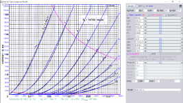
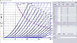
Here is 235L triode model:
Code:
**** 235L ** Advanced Grid Current **********************************
* Created on 11/02/2020 15:12 using paint_kit.jar 3.1
* [URL="http://www.dmitrynizh.com/tubeparams_image.htm"]Model Paint Tools: Trace Tube Parameters over Plate Curves, Interactively[/URL]
* Plate Curves image file: 235L.png
* Data source link:
*----------------------------------------------------------------------------------
.SUBCKT TRIODE_235L 1 2 3 ; Plate Grid Cathode
+ PARAMS: CCG=18P  CGP=1.2P CCP=9P
+ MU=5.483 KG1=632.1 KP=34.5 KVB=305.7 VCT=0 EX=1.519
+ VGOFF=-0.6 IGA=0.001 IGB=0.3 IGC=8 IGEX=2.02
* Vp_MAX=200 Ip_MAX=300 Vg_step=2.5 Vg_start=0 Vg_count=15
* Rp=4000 Vg_ac=55 P_max=16 Vg_qui=-48 Vp_qui=300
* X_MIN=62 Y_MIN=24 X_SIZE=777 Y_SIZE=585 FSZ_X=1296 FSZ_Y=736 XYGrid=false
* showLoadLine=n showIp=y isDHT=n isPP=n isAsymPP=n showDissipLimit=y
* showIg1=y gridLevel2=y isInputSnapped=n
* XYProjections=n harmonicPlot=n dissipPlot=n
*----------------------------------------------------------------------------------
E1 7 0 VALUE={V(1,3)/KP*LOG(1+EXP(KP*(1/MU+(VCT+V(2,3))/SQRT(KVB+V(1,3)*V(1,3)))))}
RE1 7 0 1G  ; TO AVOID FLOATING NODES
G1 1 3 VALUE={(PWR(V(7),EX)+PWRS(V(7),EX))/KG1}
RCP 1 3 1G   ; TO AVOID FLOATING NODES
C1 2 3 {CCG} ; CATHODE-GRID
C2 2 1 {CGP} ; GRID=PLATE
C3 1 3 {CCP} ; CATHODE-PLATE
RE2 2 0 1G
EGC 8 0 VALUE={V(2,3)-VGOFF} ; POSITIVE GRID THRESHOLD
GG 2 3 VALUE={(IGA+IGB/(IGC+V(1,3)))*(MU/KG1)*(PWR(V(8),IGEX)+PWRS(V(8),IGEX))}
.ENDS
*$
Attachments
Last edited:
Hi all
God news for those who like cheap russian tubes
Here my model for the 6N3P...
Hi Adrian, and thanks for the model!
FWIW, here are the interelectrode capacitances for 6N3P, from a datasheet I have.
*Caps
C1 A G {1.6p}
C2 A K {1.4p}
C3 G K {2.8p}
I've attached the datasheet pdf.
Attachments
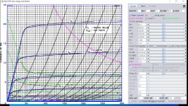
Here is 4654 model:
Code:
**** 4654 ******************************************
* Created on 11/05/2020 04:39 using paint_kip.jar
* [url=http://www.dmitrynizh.com/tubeparams_image.htm]Model Paint Tools: Trace Tube Parameters over Plate Curves, Interactively[/url]
* Plate Curves image file: 4654.png
* Data source link: <plate curves URL>
*----------------------------------------------------------------------------------
.SUBCKT 4654 P G2 G K ; LTSpice tetrode.asy pinout
* .SUBCKT 4654 P G K G2 ; Koren Pentode Pspice pinout
+ PARAMS: MU=11 KG1=1524.89 KP=53.37 KVB=12 VCT=0.2 EX=1.433 KG2=1117.2 KNEE=451.17 KVC=1.571
+ KLAM=2.4E-7 KLAMG=3.62E-4  KD=0.08622 KC=0.0504 KR1=0.004576 KR2=0.04416 KVBG=2.625E-4 KB1=2.56 KB2=2.82 KB3=2 KB4=0.32 KVBGI=0.00134 KNK=0.1444 KNG=0.00925 KNPL=5.646E-5 KNSL=0.04002 KNPR=17.92 KNSR=48.55
+ CCG=14.5P CGP=0.8P CCP=10P VGOFF=-0.6 IGA=0.00101 IGB=0.3 IGC=8 IGEX=2
* Vp_MAX=500 Ip_MAX=175 Vg_step=5 Vg_start=0 Vg_count=20
* X_MIN=58 Y_MIN=53 X_SIZE=770 Y_SIZE=539 FSZ_X=1296 FSZ_Y=736 XYGrid=false
* Rp=1400 Vg_ac=20 P_max=18 Vg_qui=-47.5 Vp_qui=300
* showLoadLine=n showIp=y isDHP=n isPP=n isAsymPP=n isUL=n showDissipLimit=y
* showIg1=y isInputSnapped=y addLocalNFB=n
* XYProjections=n harmonicPlot=y dissipPlot=n
* UL=0.43 EG2=275 gridLevel2=y addKink=y isTanhKnee=n advSigmoid=y
*----------------------------------------------------------------------------------
RE1  7 0  1G    ; DUMMY SO NODE 7 HAS 2 CONNECTIONS
E1   7 0  VALUE=  ; E1 BREAKS UP LONG EQUATION FOR G1.
+{V(G2,K)/KP*LOG(1+EXP((1/MU+(VCT+V(G,K))/SQRT(KVB+V(G2,K)*V(G2,K)))*KP))}
RE2  6 0  1G    ; DUMMY SO NODE 6 HAS 2 CONNECTIONS
E2  6 0  VALUE={(PWR(V(7),EX)+PWRS(V(7),EX))} ; Kg1 times KIT current
E4   8 0  VALUE={V(P,K)/KNEE/(KVBGI+V(6)*KVBG)}
E5  81 0  VALUE={PWR(V(8),KB1)}
E6  82 0  VALUE={PWR(V(8),KB2)}
E7  83 0  VALUE={PWR(V(8),KB3)}
E8   9 0  VALUE={PWR(1-EXP(-V(81)*(KC+KR1*V(82))/(KD+KR2*V(83))),KB4)*1.5708}
RE4  8 0  1
RE5 81 0  1
RE6 82 0  1
RE7 83 0  1
RE8  9 0  1
RE21 21 0 1
E21  21 0 VALUE={V(6)/KG1*V(9)} ; Ip with knee but no slope and no kink
RE22 22 0 1 ; E22: kink curr deviation for plate
E22  22 0 VALUE={V(21)*LIMIT(KNK-V(G,K)*KNG,0,0.3)*(-ATAN((V(P,K)-KNPL)/KNSL)+ATAN((V(P,K)-KNPR)/KNSR))}
G1   P K  VALUE={V(21)*(1+KLAMG*V(P,K))+KLAM*V(P,K) + V(22)}
G2   G2 K  VALUE={V(6)/KG2*(KVC-V(9))/(1+KLAMG*V(P,K)) - V(22)}
RCP  P K  1G     ; FOR CONVERGENCE
C1   K G  {CCG}  ; CATHODE-GRID 1
C2   G P  {CGP}  ; GRID 1-PLATE
C3   K P  {CCP}  ; CATHODE-PLATE
RE23 G 0 1G
GG G K VALUE={(IGA+IGB/(IGC+V(P,K)))*(MU/KG1)*
+(PWR(V(G,K)-VGOFF,IGEX)+PWRS(V(G,K)-VGOFF,IGEX))}
.ENDS
*$
Attachments
This update improved convergence of 4654 model by readjusting the KNEE and aligned bottom line (-25V) closer to curve.
Code:
**** 4654 ******************************************
* Created on 11/06/2020 01:51 using paint_kip.jar
* [url=http://www.dmitrynizh.com/tubeparams_image.htm]Model Paint Tools: Trace Tube Parameters over Plate Curves, Interactively[/url]
* Plate Curves image file: 4654.png
* Data source link: <plate curves URL>
*----------------------------------------------------------------------------------
.SUBCKT 4654 P G2 G K ; LTSpice tetrode.asy pinout
* .SUBCKT 4654 P G K G2 ; Koren Pentode Pspice pinout
+ PARAMS: MU=11 KG1=1570.64 KP=62.98 KVB=12 VCT=0.2 EX=1.433 KG2=1117.2 KNEE=64581.56 KVC=1.571
+ KLAM=2.4E-7 KLAMG=4.561E-4  KD=0.6732 KC=7.709 KR1=0.004576 KR2=0.004416 KVBG=7.547E-6 KB1=2.483 KB2=2.82 KB3=2 KB4=0.3136 KVBGI=2.144E-4 KNK=0.07131 KNG=0.01036 KNPL=4.63E-5 KNSL=0.04802 KNPR=31.54 KNSR=54.38
+ CCG=14.5P CGP=0.8P CCP=10P VGOFF=-0.6 IGA=0.00101 IGB=0.3 IGC=8 IGEX=2
* Vp_MAX=500 Ip_MAX=175 Vg_step=5 Vg_start=0 Vg_count=20
* X_MIN=59 Y_MIN=67 X_SIZE=770 Y_SIZE=539 FSZ_X=1296 FSZ_Y=736 XYGrid=false
* Rp=1400 Vg_ac=20 P_max=18 Vg_qui=-47.5 Vp_qui=300
* showLoadLine=n showIp=y isDHP=n isPP=n isAsymPP=n isUL=n showDissipLimit=y
* showIg1=y isInputSnapped=y addLocalNFB=n
* XYProjections=n harmonicPlot=y dissipPlot=n
* UL=0.43 EG2=275 gridLevel2=y addKink=y isTanhKnee=n advSigmoid=y
*----------------------------------------------------------------------------------
RE1  7 0  1G    ; DUMMY SO NODE 7 HAS 2 CONNECTIONS
E1   7 0  VALUE=  ; E1 BREAKS UP LONG EQUATION FOR G1.
+{V(G2,K)/KP*LOG(1+EXP((1/MU+(VCT+V(G,K))/SQRT(KVB+V(G2,K)*V(G2,K)))*KP))}
RE2  6 0  1G    ; DUMMY SO NODE 6 HAS 2 CONNECTIONS
E2  6 0  VALUE={(PWR(V(7),EX)+PWRS(V(7),EX))} ; Kg1 times KIT current
E4   8 0  VALUE={V(P,K)/KNEE/(KVBGI+V(6)*KVBG)}
E5  81 0  VALUE={PWR(V(8),KB1)}
E6  82 0  VALUE={PWR(V(8),KB2)}
E7  83 0  VALUE={PWR(V(8),KB3)}
E8   9 0  VALUE={PWR(1-EXP(-V(81)*(KC+KR1*V(82))/(KD+KR2*V(83))),KB4)*1.5708}
RE4  8 0  1
RE5 81 0  1
RE6 82 0  1
RE7 83 0  1
RE8  9 0  1
RE21 21 0 1
E21  21 0 VALUE={V(6)/KG1*V(9)} ; Ip with knee but no slope and no kink
RE22 22 0 1 ; E22: kink curr deviation for plate
E22  22 0 VALUE={V(21)*LIMIT(KNK-V(G,K)*KNG,0,0.3)*(-ATAN((V(P,K)-KNPL)/KNSL)+ATAN((V(P,K)-KNPR)/KNSR))}
G1   P K  VALUE={V(21)*(1+KLAMG*V(P,K))+KLAM*V(P,K) + V(22)}
G2   G2 K  VALUE={V(6)/KG2*(KVC-V(9))/(1+KLAMG*V(P,K)) - V(22)}
RCP  P K  1G     ; FOR CONVERGENCE
C1   K G  {CCG}  ; CATHODE-GRID 1
C2   G P  {CGP}  ; GRID 1-PLATE
C3   K P  {CCP}  ; CATHODE-PLATE
RE23 G 0 1G
GG G K VALUE={(IGA+IGB/(IGC+V(P,K)))*(MU/KG1)*
+(PWR(V(G,K)-VGOFF,IGEX)+PWRS(V(G,K)-VGOFF,IGEX))}
.ENDS
*$I have downloaded the file from 6/29/2018. Looks great - thank you.
Is there any later compilation listing other tubes that have been shared in this thread (or elsewhere)? It's painful to attempt to search for each tube one by one and I'm not quite ready to make my own models.
Is there any later compilation listing other tubes that have been shared in this thread (or elsewhere)? It's painful to attempt to search for each tube one by one and I'm not quite ready to make my own models.
- Home
- Amplifiers
- Tubes / Valves
- Vacuum Tube SPICE Models