Hi all!
I bought a PCB from Ebay for a standard EL34 PP amp. I have built those before so i thought if i could improve it with a ccs. I really have no idea what i'm doing but") I have built with ccs before (TubelabSE) but never understand how it works.
I have built with ccs before (TubelabSE) but never understand how it works.
Anyway..
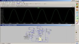
Will this work? Will it improve the amp? Before it was a 22K resistor.
How should i know what mA i want from the css? Is it correct calculated that this will draw 6mA totally (3mA per side)?
Sorry for all the questions...
Regards //Daniel
I bought a PCB from Ebay for a standard EL34 PP amp. I have built those before so i thought if i could improve it with a ccs. I really have no idea what i'm doing but
I have built with ccs before (TubelabSE) but never understand how it works.Anyway..
An externally hosted image should be here but it was not working when we last tested it.
Will this work? Will it improve the amp? Before it was a 22K resistor.
How should i know what mA i want from the css? Is it correct calculated that this will draw 6mA totally (3mA per side)?
Sorry for all the questions...
Regards //Daniel
I bought a PCB from Ebay for a standard EL34 PP amp. I have built those before so i thought if i could improve it with a ccs. I really have no idea what i'm doing but
Run, do not walk, and get a copy of Valve Amplifiers 4th edition. In it you will find full explanations of CCS and why you can't drop it into the circuit without changing some plate resistors. I'd guess from the values there that the original cathode resistor was about 18k.
It should work a bit better: improved symetry to drive the power stage, you may like or dislike (less even harmonics generated).
Your emiter resistor is correct for 2 x 3mA, just keep in mind that the MjE340 will have to sustain about 140V and will dissipate near 1 Watt.
Yves.
Oh ! I feel alone
Your emiter resistor is correct for 2 x 3mA, just keep in mind that the MjE340 will have to sustain about 140V and will dissipate near 1 Watt.
Yves.
Oh ! I feel alone
Last edited:
improved symetry to drive the power stage
Not with the plate resistors on the schematic- this will be more unbalanced than the original since the tail is too good. Changing the plate resistors to equality will bring things back in line. The feedback here is way too low as well.
Of course, that doesn't change my recommendation that the O/P try to understand the "why" better.
Thanks all for your answers!
I will get the bibel ( 4th edition..) read it, and try to understand it but i want to understand, order parts and build now!!
Ok, so the anodresistors need to be equal. And in the original schematic the resistor was 22k so it was close SY
B+ will be 450v then drop 2.2k for B1 and 150k to B2.
Fine that i got the emiter resistor right..(for 6mA, if that is correct?)! Always a start..
Regards //Daniel
I will get the bibel ( 4th edition..) read it, and try to understand it
but i want to understand, order parts and build now!! Ok, so the anodresistors need to be equal. And in the original schematic the resistor was 22k so it was close SY
B+ will be 450v then drop 2.2k for B1 and 150k to B2.
Fine that i got the emiter resistor right..(for 6mA, if that is correct?)! Always a start..
Regards //Daniel

Is RDH4 out of fashion? No semiconductors, but the principles of valve circuits are dealt with comprehensively.
http://www.tubebooks.org/Books/RDH4.pdf
http://www.tubebooks.org/Books/RDH4.pdf
Last edited:
Is RDH4 out of fashion?
Yes and no. The omission of solid state is fine for 1955, not so much for today, where we have a wonderful array of devices that are perfect for constant voltage and constant current. As well, VA4 is much better on questions of noise, RIAA, and modern passive components. RDH4 is a great reference manual, VA4 is a great learning tool.
RDH4 covers magnetics and RF in far more detail. VA4 is much more focused on audio circuitry.
Ok cool.
Just making sure its not a 5 parter and I'd find out how it ended before I knew how it started.
Thanks.
If you find yourself up in Grayslake and want a preview, drop me an email.
Thanks for replying, I hope you'll get your board soon.
I have a pair of James 6225HS along with a vintage DuKane transformer with the secondary voltage of 400v ac at about 200ma which i'm planning to use. I haven't decided on the power supply and haven't bought the tubes yet, but in the next few weeks I'll be ready to go!
Regards
farhun
I have a pair of James 6225HS along with a vintage DuKane transformer with the secondary voltage of 400v ac at about 200ma which i'm planning to use. I haven't decided on the power supply and haven't bought the tubes yet, but in the next few weeks I'll be ready to go!
Regards
farhun
- Status
- This old topic is closed. If you want to reopen this topic, contact a moderator using the "Report Post" button.
- Home
- Amplifiers
- Tubes / Valves
- Will this work? (EL34 PP)