Hello all,
I am finally getting ready to start an amp project that I have been planning for years...A Quicksilver 8417 with either KT88 or EL34 (got em both - the 8417 tube was way out of my reach). I planned on using the directions from Triode Electronics website that convert the 8417 circuit to a KT88 or a EL34 (bias resistors, grid resistors, etc).
But need some advice - I know the original had the 12AX7 and the 12BH7, but I found some 6N1P, 6H30, 6922, 12AU7, and 12AT7 in my stash of tubes (as well as the 12AX7 and 12BH7 I need to complete the amp)....wondering if anyone has some advice what I could make that would best the 8417.
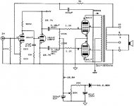
The schematic for the 8417 is attached. I have a pair of Edcor 4.2k 60W P-P output trannies, a pair of Edcor power Tranny (B+ should be around 500V), and the pair of 1.5 chokes...
I'm thinking a 6922 input amp and 6H30 Phase Splitter would be the best combo??
I am finally getting ready to start an amp project that I have been planning for years...A Quicksilver 8417 with either KT88 or EL34 (got em both - the 8417 tube was way out of my reach). I planned on using the directions from Triode Electronics website that convert the 8417 circuit to a KT88 or a EL34 (bias resistors, grid resistors, etc).
But need some advice - I know the original had the 12AX7 and the 12BH7, but I found some 6N1P, 6H30, 6922, 12AU7, and 12AT7 in my stash of tubes (as well as the 12AX7 and 12BH7 I need to complete the amp)....wondering if anyone has some advice what I could make that would best the 8417.
The schematic for the 8417 is attached. I have a pair of Edcor 4.2k 60W P-P output trannies, a pair of Edcor power Tranny (B+ should be around 500V), and the pair of 1.5 chokes...
I'm thinking a 6922 input amp and 6H30 Phase Splitter would be the best combo??
Attachments
So you want to build a particular design, but you want to change every active device in it to something different (with presumably knock-on effects on passive component values too). In what sense are you still building that design rather than simply a different circuit which happens to share the same (fairly common) architecture?
Question was really around a possible better tube choice, as I don't really like seeing a 12AX7 in the amps "pole position". I have read that the 6H30 makes a great splitter, and I have one. Worth the swap?
8417 tubes are expensive, and not easy to source. If I had them, I would use them...
Is that your advice? Stick to the original? OK. Thanks.
8417 tubes are expensive, and not easy to source. If I had them, I would use them...
Is that your advice? Stick to the original? OK. Thanks.
The 12AX7 is an excellent linear voltage amplifier in the right circuit. It needs a high impedance load, so either a CCS or a highish supply rail and a high value anode resistor. 439V should be enough. Using a 6922 as input stage would reduce the open loop gain so increasing the closed loop distortion.
That type of phase splitter has so much negative feedback that it will provide low distortion with almost any valve, apart from very high mu ones (such as 12AX7).
That type of phase splitter has so much negative feedback that it will provide low distortion with almost any valve, apart from very high mu ones (such as 12AX7).
OK, I will reconsider the 12AX7....Stick with the 12BH7 as the splitter?
The 12BH7 and 6H30 have close mu (17 vs 15), and maybe not a big deal enough to change it...
The 6H30 is that tube everyone always talks about, so it has that ooh - ahhh factor ...but can anyone really hear differences in a phase splitter??
The 12BH7 and 6H30 have close mu (17 vs 15), and maybe not a big deal enough to change it...
The 6H30 is that tube everyone always talks about, so it has that ooh - ahhh factor ...but can anyone really hear differences in a phase splitter??
The thing to watch out for is voltage swing. The proposed new output tubes have lower gain than 8417, so require more grid voltage. The cathodyne has gain somewhat lower than unity, so the first stage has to swing the peak to peak requirement of the output stage plus the voltage "used up" by the cathodyne (which is significant for lower mu triodes). Then all of that has to be within the reach of the cathodyne as well.
The original design has high gain output tubes as well as high gain triode as a voltage amplifier.
You plan to use 6922 (mu = 33) as voltage amplifier and EL34 as output tubes having gm = 12,5 mA/V, which is some 60 % of the gm of 8417.
This means that the whole "gain plan" is very far from the original desing.
If also some amount of GNFB is used, the sensitivity of the amplifier could be several volts (rms) to have full power.
One clear fault - especially with different output tubes - is the direct connection between voltage amplifying stage and cathodyne. These should be separated and biased individually.
Dunno... I'm just fond of not letting one "hanging triode" do all the phase shaping. My advice - since DF96 said it first - is that since you're potentially willing to change most of the circuit path to fit your bottles ... is that you shoot for much more modest gain at the first stage, then use a 12AU7 as a 2nd gain stage, giving larger voltage swing and making more symmetric the 'signal shaping' of the triode on the signal. Hardly makes the circuit more complicated - just another triode stage and a DC blocking cap of high quality - and you're home free. Take the square root of intended "first stage gain", and let each triode be responsible for that part. Gain can be raised a bit overall (addressing various other comments) to better match your non-original-spec output tubes.
And to think: your project will have yet another cute little glowing glass jug of vacuum goodness on the topside! Worth it at near-any cost!
GoatGuy
And to think: your project will have yet another cute little glowing glass jug of vacuum goodness on the topside! Worth it at near-any cost!
GoatGuy
Yep that works too.
The reason that 300K resistor is hanging off the first-stage 12AX7 is to maximize gain to the near-limit. Choosing a pair of finals with lower mu ... increases the need for gain yet more. You could however, drive them at higher current draw ... with a little math work, and a slightly different transformer. So... use the KT88's. They're really quite nice.
GoatGuy
...The reason that 300K resistor is hanging off the first-stage 12AX7 is to maximize gain to the near-limit....
GoatGuy
Actually, no it isn't.
The reason for such high resistance is to bias the direct connected phase splitter to near optimum operating point. This kind of circuit is a compromise.
Both stages should be biased individually, as I have said earlier.
If the gain of 12AX7 stage wanted to be increased or maximized, it can simply be done by bypassing the 820 ohms cathode resistor with some 100 uF electrolyte.
This increases the gain some 2 dB.
Last edited:
Actually, no it isn't.
The reason for such high resistance is to bias the direct connected phase splitter to near optimum operating point. This kind of circuit is a compromise.
Both stages should be biased individually, as I have said earlier.
If the gain of 12AX7 stage wanted to be increased or maximized, it can simply be done by bypassing the 820 ohms cathode resistor with some 100 uF electrolyte.
This increases the gain some 2 dB.
Actually, it's both. The resistance is chosen to achieve the correct bias point for the following stage, but the supply voltage is made high enough to make that resistance very high to provide a high gain for the first stage. Bypassing the cathode resistor is just a small trick to get a little more gain in exchange for a lot more distortion. Like I said before, the Williamson circuit is superior to this thing anyway.
Yes.dirkwright said:Actually, it's both.
Not necessarily. You would get a little more distortion in the input stage, but enough extra gain to reduce the much greater distortion from the output stage. There could be an effect on common-mode distortion in the first stage; bypassing might make this worse. The exact balance of advantage depends on details. Mullard and Leak always bypassed the first stage cathode resistor.Bypassing the cathode resistor is just a small trick to get a little more gain in exchange for a lot more distortion.
The key point seems to be forgotten.
Direct connected voltage amplifier and cathodyne phase splitter is a compromise.
It is working well only when a pentode amplifier is used, since this operates at optimum point with sufficiently low anode voltage.
Therefore both should be biased and optimised separately.
Direct connected voltage amplifier and cathodyne phase splitter is a compromise.
It is working well only when a pentode amplifier is used, since this operates at optimum point with sufficiently low anode voltage.
Therefore both should be biased and optimised separately.
In this circuit adding a coupling cap would add an LF pole and possibly compromise LF stability. However, a DC potential divider with the upper resistor bypassed by a cap should be OK. That would give some separation of stages, at the expense of adding loading to the first stage. Once again, it all depends on details.
I think you'd be better off building a Williamson clone. But, that's just my opinion.
That's mine too. Quicksilver amps are among the worst commercial amps I have listened to. In my opinion they gained some popularity just because they came out in a time where tube amps only represented a niche and there were not too many around.
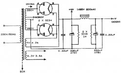
I have a friend who had the version with KT88's and he had to change the rectifiers every year! Really bad design. From the schematics it is easy to see why his rectifiers had short life. They were expensive and didn't sound good at all to me. The other models are not so much better....
Attachments
- Status
- This old topic is closed. If you want to reopen this topic, contact a moderator using the "Report Post" button.
- Home
- Amplifiers
- Tubes / Valves
- Quicksilver 8417 Design - Stay with it or modify?