Friends. I have a nice little amp that sings like a bird but it has a built in motorboat. The bass cones moves at a frequency of half a Hz or so. Usually boating in my experience is fast/slow cap oscillations but I can be wrong.
Unbashedly I'm throwing up a thread looking for advices on how/where to search, what to test. Beleave me I have searched and changed all kind of stuff but I still havent found root cause.
I can say it needs a signal to start boating, without signal it is calm. When I change ECC83s to ECC81s for test it goes away. I have rebuilt PSU many times, I have mounted G2 stoppers, changed tubes etc but nothing helps.
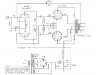
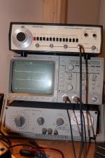
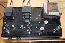
Attatching some info. The basic circuit (Dave Haflers commercial paper for Dynaco OPTs), The DUT and some tools I have handy. I dont have a 10k gridstopper on input but one 1k on each grid instead and have added some 150Rs on G2s.
What would you search for? Please ask on what I forgot to announce.
Best regards
Staffan
Unbashedly I'm throwing up a thread looking for advices on how/where to search, what to test. Beleave me I have searched and changed all kind of stuff but I still havent found root cause.
I can say it needs a signal to start boating, without signal it is calm. When I change ECC83s to ECC81s for test it goes away. I have rebuilt PSU many times, I have mounted G2 stoppers, changed tubes etc but nothing helps.
Attatching some info. The basic circuit (Dave Haflers commercial paper for Dynaco OPTs), The DUT and some tools I have handy. I dont have a 10k gridstopper on input but one 1k on each grid instead and have added some 150Rs on G2s.
What would you search for? Please ask on what I forgot to announce.
Best regards
Staffan
Attachments


ignoring obvious mess of wires , simple test will reveal some things - feed input triodes with reged voltage ; simple zener based reg will suffice
Whats a simple zener reg then? 2 150 in series to gnd?
Additional info: I dont have any ringing-killer cap on GNF. I built it when I didnt have a scope.
Last edited:
The loop gain is lower when ECC81 is used instead of ECC83. Then the GNFB is also lower.
One solution is to lower the amount of GNFB by increasing the present NFB-resistor (1k).
But have you tried essentially larger cathode capacitor at the output tubes ?
Some 220...470 uF may help.
Another thing you could check is to increase both 100nF coupling capacitors from ECC83 to EL84 to some 470n....
Do only one modification at a time and test.
The loop gain is lower when ECC81 is used instead of ECC83. Then the GNFB is also lower.
One solution is to lower the amount of GNFB by increasing the present NFB-resistor (1k).
But have you tried essentially larger cathode capacitor at the output tubes ?
Some 220...470 uF may help.
Another thing you could check is to increase both 100nF coupling capacitors from ECC83 to EL84 to some 470n....
Do only one modification at a time and test.
Good advices. I have not tried any of them and I will. All at once
") No, one at a time
No, one at a timewhat is possibility of foil failure in cap ?
Could be. I tried adding 470 u to the 47 common cathode caps, didnt help. I soldered in 2k2 on gnf instead of 1 k bit didnt have time to test it. Son-dad time. I also layed up some 330 nF couplings for mounting. Maybe later, probably tomorrow. Thanks!
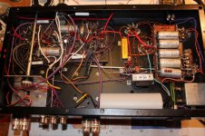
Hey Stajo, not sure from the photo but your grounding scheme seems a bit random ie you did your grounding the way you built it? I would recommend that you sort it before any other modifications. Looks like you have room to go to a star ground or a tree of stars. I'm sure there's a lengthy thread on here about grounding.
Cheers Matt.
Cheers Matt.
Friends! The boating seems to go away with decreased GNF/increased resistor (2k4 instead of 1k atm). Im gonna let it play a while and see if its stable.
I think the sound firmed up a little to, not as wet and fluffy as before.
Any suggestions on how to get to optimum values? Just try until I'm satisfied? Scope and find an optimum squarewave with random decoupling caps?
I think the sound firmed up a little to, not as wet and fluffy as before.
Any suggestions on how to get to optimum values? Just try until I'm satisfied? Scope and find an optimum squarewave with random decoupling caps?
Hi Stajo,
Changing the 1k resistor in the feedback to a 2.4k also moves the 12AX7 operating point - that circuit uses the feedback resistor to set the grid bias. Might have fixed the motorboating, but could cause other problems.
You may know that already, but I was wondering if you had checked the 12AX7 bias voltages after your change to make sure your operating range is still sufficient.
Also, you might try going back to the 1k feedback resistor (which seems to be the "normal" feedback resistor value for that circuit) and increasing the 100uF cathode bypass cap on the 12AX7.
Increase it to 200uF or 300uF. The cathodes should be at AC ground, but at 1Hz the 100uF cathode bypass impedance is about 1600ohms which may be too high.
Sam
EDIT - Well, ONE of the cathodes should be at AC ground. The other is 100 ohms resistive above AC ground. Minor point, just being clear.
Anyway, I think this was a commercial design so cost was a consideration so they didn't go overboard with parts values. Since this is a DIY project you, of course, have the option to increase the design margins a bit.
Good luck!
EDIT 2 - I saw that Artosalo recommended increasing the cathode bypass on the output tubes. Just to be clear, I'm recommending increasing the cathode bypass on the input 12AX7 tube - I think that may be where your problem is.
I think I would also separate the cathode bias on the output tubes - running them in common is another commercial practice to save money which we can spend like Midas on these DIY projects - but that is another story and " if it ain't broke don't fix it " is the best approach here
Last edited:
Try,
Putting the feedback on the 8 ohm tap to see what happens...leave everything else standard just to try it..
Change grounding to Star grounding..does it do it with no connection to other inputs and the input turned to different levels..you also seem to have output and input very close.... Keep output gnd as close to earth as possible no variation in Gnd resistance. Variation in Gnd resistance creates a voltage drop and possible voltages in the ground system.
Regards
M. Gregg
Last edited:
When you say it I have the feedback on the 8 ohm tap. I dont use an original A-410 as it was designed for by Mr Hafler, but a some salvaged Z 565s.
Its been playing for a while now, and its stable. Firm and controlled in sound. Maybe a little to much controlled to my taste.
Im gonna turn it upside down later, and I find your suggestions to try to go back as close to the 1 k as it allowes. Maybe increase cathode bypass in the splitters and find me a good cap value with squarewaves over the feedback resistor (right now I have none).
Is that correctly percieved from my side?
/Staffan
Last edited:
You need to find out if its a stability issue or a grounding issue.
Might sound strange..ie is it wiring layout or is it stability created by resistance in the Gnd.
Output Gnds should be as close to Gnd/earth as possible.
The feedback resistor as stated sets the bias so it should be as close as possible..(to value)
The feedback is already lower if you are on the 8 ohm tap..
I assume the feedback is in the correct phase<<just asking
Regards
M. Gregg
Last edited:
Another thing that I find a little odd is that the completely oversized powertranny gets almost to hot to touch after some hour playing. It might be that it has some minor shorts in windings? This one should easily drive a 6L6 PPP or similar and I dont think it should be this hot on this little circuit.
About grounding it might not look star:ish but I have actually worked that a couple of time and I dont have any 50 or 100 Hz tendensies.
Excuse the dust, its been collecting a while.
About grounding it might not look star:ish but I have actually worked that a couple of time and I dont have any 50 or 100 Hz tendensies.
Excuse the dust, its been collecting a while.
Attachments
If you are already taking the feedback off the 8-ohm tap, the feedback has been reduced by 6dB from the original design. Increasing the feedback resistor to 2.4k reduces it another 6-ish dB so you're down 12dB from the original.
Seems that you would actually need to decrease the feedback resistor to get back to the original design level.
The compensating cap will almost certainly be different (from the original) due to the different output transformer, but that is a fine-tune you can do with a square-wave test.
This doesn't sound like a grounding issue to me, especially if you are not hearing other noise in your system.
Looking at the power Tx,
ER....Its not a good idea to have single cables through holes on AC supplies..
The two AC cables for each supply should come through the same hole..
I guess (two grey) two green (two black)<<each supply? (you can just cut a slot across each pair of holes to overcome this)
Whats the chassis made of?
I also don't see any isolation for the transformer mounting pins...I guess you have a shorted turn on the Iron??? (Not the windings the mountings)
Easy to check there should be no connection between each of the four mounting screws and Tx iron..with a meter set to ohms.
ie no connection across the laminations to the screws so you dont get a loop via the screws and the laminations. (shorted turn)
Does the incomming mains have a grommet (through the chassis)?
Keep Feedback and output wiring away from inputs..check phasing of feedback..
Regards
M. Gregg
Last edited:
- Status
- This old topic is closed. If you want to reopen this topic, contact a moderator using the "Report Post" button.
- Home
- Amplifiers
- Tubes / Valves
- ISO a motorboat