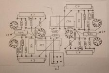
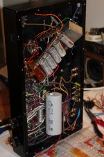
Hi. Not really. I found some, unfortunately low resolution pictures, on my physical planning layout. In the scetch, if we look at the right side the grid leaks are R19 (parallelled with a VR pot that I have now removed) and R20. The 47k is R21, directly to the lower 12AX7 grid.
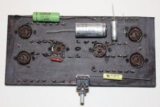
The plate that I built it on is two 2-component glued hard paper with lead ears on.
The plate that I built it on is two 2-component glued hard paper with lead ears on.
Attachments
Last edited:
I'm at some negotiation table atm so I cant check but I have some connected ground pins in between the 12AX7s and as I remember it it goes directly to them, same as the EL84rs cathodes components. Grounds are channel separated (together with the last 47 uF C in the small signal filter) up to a leadstand that is between the circuit on one side and the OPTs and RCAs on the other side where all audiocircuits meet. That one has a 2 mm copper up to PSU ground.
OK, just verify that those sections are following the schematic exactly for connections and then try to lower the 270k resistors value by // other values to see if a change can happen.
When you had a probe there it changed something, lets see what. Maybe a tighter and more symmetrical physical layout around those points will play a role even.
When you had a probe there it changed something, lets see what. Maybe a tighter and more symmetrical physical layout around those points will play a role even.
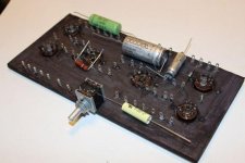
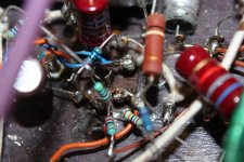
I just remembered, and verified passing by home briefly, that the "tighter and more symmetrical physical layout" was just what I tried last time I was trying to track this down. On pic (yes I know it looks like  in closeup. It does when changing stuff alot) I have putted them all, two 270K and one 47K directly on the pin as experiment.
Salas, not that I mistrust your opinion about classic oscillation, but what was it that lead you to that? The very wiggle formation on the scope, the behaviour when I moved probe or the motorboating that starts when I simulate music by pushing different frequency buttons on gen?
Though.... I found on inspection that I for some layout reason has ca 15 mm wire left between my 1k Dale unmagnetic WW gridstoppers and grids.
Is EL84 that sensitive to grid oscillation? Experiences anyone?
Well I will try to shorten them later, but I dont have the time now.
Staffan
in closeup. It does when changing stuff alot) I have putted them all, two 270K and one 47K directly on the pin as experiment.Salas, not that I mistrust your opinion about classic oscillation, but what was it that lead you to that? The very wiggle formation on the scope, the behaviour when I moved probe or the motorboating that starts when I simulate music by pushing different frequency buttons on gen?
Though.... I found on inspection that I for some layout reason has ca 15 mm wire left between my 1k Dale unmagnetic WW gridstoppers and grids.
Is EL84 that sensitive to grid oscillation? Experiences anyone?
Well I will try to shorten them later, but I dont have the time now.
Staffan
Attachments
Yea, nice! Have one for me. I got kid-grounded on my free Days cause of weak moms") . Well not that disturbing. I only hear the holler when the doodle bowl is empty or when to restart a minecraft server.
. Well not that disturbing. I only hear the holler when the doodle bowl is empty or when to restart a minecraft server.
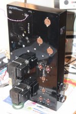
I have been putting isolating clear plastic between the OPTs and chassie, just one screw touches chassie/gnd now. Doing the same with Power Tx now. Using unmagnetic stainless screws and rubber brackets. Is thats ok?
Also freaked out an putted some reds on the splitters cathodes. And splitting Powertubes/OPTs into two filterlines. Oh, whatever... I know. To many things at once. Lets see...
Cheers!
. Well not that disturbing. I only hear the holler when the doodle bowl is empty or when to restart a minecraft server.I have been putting isolating clear plastic between the OPTs and chassie, just one screw touches chassie/gnd now. Doing the same with Power Tx now. Using unmagnetic stainless screws and rubber brackets. Is thats ok?
Also freaked out an putted some reds on the splitters cathodes. And splitting Powertubes/OPTs into two filterlines. Oh, whatever... I know. To many things at once. Lets see...
Cheers!
Take it in steps so you can verify what did the trick.
Good for education bad for the restless person.
I have a tractor with 3 missing pistons to deal with tomorrow so todays mission is to forget what comes tomorrow.
I´ll trade you piston replacement for amp repair any day.
Good luck and if all else fails.....Metaxa !!
Good for education bad for the restless person
.I have a tractor with 3 missing pistons to deal with tomorrow so todays mission is to forget what comes tomorrow.
I´ll trade you piston replacement for amp repair any day
.Good luck and if all else fails.....Metaxa !!
The amp is now stable. I isolated the Power Tx and the OPTs so their gnd connection is now more controlled. I tried with red 3 mm LEDs on the 12AX7 cathodes to be able to choose FB resistor to my taste but they were blinking and there was some strange noices.
Maybe theres to little current for a LED with a 12AX7 running some 360 V B+?
So I went back to cap decoupled kathodes, putted in 470 uF half-crappy 25V regular ones.
PSU-wise I added a filter step and splitted last to the powertubbies. 50uF-33R-4*47uF-dual 150R-dual 220uF crappy Philips 385V.
Soundwise taking FB from 16 ohm instead of 8 ohmtap naturally takes a huge portion of amplification away so I have to go to 2 o'clock to feel the sofa vibrating. Sound is also a microportion duller. I think to excessive B+ filtering is bad boy there. Push-Pull shall balance ripple out instead of filter it in PSU. Gives more attack.
The 12AX7 has now some 360 V B+ which might be a little on the edge but it works so.
Thanks for help guys. Maybe I give it some measures later. Now to decide next project. Finish my Salas 6V6 pre to be common room friendly, making a PPP version of this or go ahead with some donut SS amps. Or all at once as usual?!?
Well you will know
Staffan
Congrats back then, you greaser good that cranc and top was ok then. Yea its nice to have something working, this is my only tubeamp that likes the 6V6 pre that I've got at home (or vice versa). It will give it the nexessary extra push.
Why did you order this rain? I was thinking of drinking up your beer
good that cranc and top was ok then. Yea its nice to have something working, this is my only tubeamp that likes the 6V6 pre that I've got at home (or vice versa). It will give it the nexessary extra push.Why did you order this rain? I was thinking of drinking up your beer
- Status
- This old topic is closed. If you want to reopen this topic, contact a moderator using the "Report Post" button.
- Home
- Amplifiers
- Tubes / Valves
- ISO a motorboat