Some concerns from the schematic:
Did you ask for a 150W peak or RMS power handling?
For KT120 duty you need 51k grid leak resistors. You have 100k plus up to 225k ohms worth of resistance to ground from the control grid through the bias circuit. You need to rescale your bias circuit so it is less than 51k to ground for KT120 tubes. It is even pushing it for KT88s. The recommend a minimum of 220k.
I have the same output transformer it seems, I told him to make it sized for 150w, but from the looks of your power transformer it has a bit more thickness in the core then mine. When I get the next one I will have him make it a bit bigger as it seems to run a bit hot even when not running the 5U4's which would be another 30 watts of power dissipation.
Did you ask for a 150W peak or RMS power handling?
For KT120 duty you need 51k grid leak resistors. You have 100k plus up to 225k ohms worth of resistance to ground from the control grid through the bias circuit. You need to rescale your bias circuit so it is less than 51k to ground for KT120 tubes. It is even pushing it for KT88s. The recommend a minimum of 220k.
For the power transformer just gave him voltage and current. That is the one that looks smaller, I think you spec'ed your for more current. On the output transformer it looks similar sized as yours, but I just said 150watts when I ordered it.
I never noticed the spec for the grid leak resistors. What effect does having them too high cause? And is it just the resistance to GND or to the Bias- that the target.
In long term don't plan on using KT120's but would like to always make things better, is it just a matter of dropping them (just the grid resistors) to 51k.
Last question what goes wrong if they are not 51k, more distortion or tube life issues?
Thanks for all the help as well.
Sandy
What happens to my knowledge is a phenomenon known as thermal runaway.
The grid always sinks some current. If allowed to go unchecked, the tube will conduct more, causing greater grid current, causing greater conduction, resulting in a tube that overheats. A similar effect occurs with FETs due to impurities in the SiO2 layer between the gate and the junction.
Tubes 201 - How Vacuum Tubes Really Work
You can tell this is happening when the bias current drifts up slowly over time. Changing out the resistors is no big deal. Just scale them down so they are 10-25% of the ones you have there now.
Last edited:
Current production KT88 and KT120 can not handle more than 50 K grid resistors.
The Nos KT88 could, but even so lasted longer if you used 50K.
Even GEC for their 8X Kt88 had 38K.. very similar to the circuit shown By Sandy G.
some commercial circuits use 100k; I have even seen 1Meg, the chassis was full of sootsootfrom tubes that
Phil
The Nos KT88 could, but even so lasted longer if you used 50K.
Even GEC for their 8X Kt88 had 38K.. very similar to the circuit shown By Sandy G.
some commercial circuits use 100k; I have even seen 1Meg, the chassis was full of sootsootfrom tubes that
Phil
GEC 8 x kt88
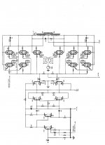
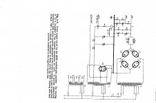
Circuit of GEC KT88 x 8. I built it using 4 x 6550's. The original uses GXU1 rectifiers, but have found you don't need choke input, silicon rectifiers with cap input give excellent regulation; I used an adjustable load two 3k 200 watt pots.to test the power transformers. I guess even better if your power tran has sufficient voltage to use choke input.
Phil
Attachments
That GE circuit with the 10 x KT88s .......
One needs to be more careful. It feeds 47K grid resistors from 47K cathode follower loads? No voltages are given, but that makes for a nasty ac load on the drivers. Unless one has more current through the drivers than the 3,7W dissipation for 6SN7s will allow, quite a bit of distortion shows up from the load lines. OK, they are cathode followers, but it is not wise to have distortion from the basic topology and then glibly cancelling it with feedback. (That apart from 47K grid resistors for 5 x KT88s in parallel?)
The solution is not easy. With a required grid drive of some 50 - 60Vp signal, one is approaching using power tubes for drivers or increasing the h.t., or using several triodes in parallel for drivers as someone suggested. As said before (I think!), I ran into such a difficulty with four 6L6s, and had to revert to a servo circuit to keep the power tubes from running away. (In my case I needed 300K min. required for grid resistors without which the drivers would have generated excessive distortion).
In this modern era there is no excuse for shoddy drivers and/or excess grid 1 to 0V resistance. Use one Mosfet Source follower per output tube. Current Source load the source followers, a "ring of two" bipolar transistor current source is adequate. Apply the bias to the gate of the mosfet. Choose MOSFET drain volts to keep a minimum of 25V across the mosfet on peak positive signal drive (so that Crss modulation is minimized). Returm the current source to a V- of at least x3 the bias voltage. Use a mosfet of only as large as you need NOT an IRF820 etc. (You want small Crss).
My next project will be2 off 4 x KT88 Monoblocks with 30% Ultralinear and 10% Cathode Feedback using Plitron VDV2100-CFB/H Output Trannies which I have on my shelf ready to go (with matching Power Trannies).
Cheers,
Ian
My next project will be2 off 4 x KT88 Monoblocks with 30% Ultralinear and 10% Cathode Feedback using Plitron VDV2100-CFB/H Output Trannies which I have on my shelf ready to go (with matching Power Trannies).
Cheers,
Ian
That GE circuit with the 10 x KT88s .......
One needs to be more careful. It feeds 47K grid resistors from 47K cathode follower loads? No voltages are given, but that makes for a nasty ac load on the drivers. Unless one has more current through the drivers than the 3,7W dissipation for 6SN7s will allow, quite a bit of distortion shows up from the load lines. OK, they are cathode followers, but it is not wise to have distortion from the basic topology and then glibly cancelling it with feedback. (That apart from 47K grid resistors for 5 x KT88s in parallel?)
The solution is not easy. With a required grid drive of some 50 - 60Vp signal, one is approaching using power tubes for drivers or increasing the h.t., or using several triodes in parallel for drivers as someone suggested. As said before (I think!), I ran into such a difficulty with four 6L6s, and had to revert to a servo circuit to keep the power tubes from running away. (In my case I needed 300K min. required for grid resistors without which the drivers would have generated excessive distortion)
John Potgieter.
I used two 6BL7 instead of the one 6SN7' and the Russian 6n6 or 12BH7's. with 38k bias resistors.
The 6550's have lasted for 10 years.
Phil
That GE circuit with the 10 x KT88s .......
One needs to be more careful. It feeds 47K grid resistors from 47K cathode follower loads? No voltages are given, but that makes for a nasty ac load on the drivers. Unless one has more current through the drivers than the 3,7W dissipation for 6SN7s will allow, quite a bit of distortion shows up from the load lines. OK, they are cathode followers, but it is not wise to have distortion from the basic topology and then glibly cancelling it with feedback. (That apart from 47K grid resistors for 5 x KT88s in parallel?)
The solution is not easy. With a required grid drive of some 50 - 60Vp signal, one is approaching using power tubes for drivers or increasing the h.t., or using several triodes in parallel for drivers as someone suggested. As said before (I think!), I ran into such a difficulty with four 6L6s, and had to revert to a servo circuit to keep the power tubes from running away. (In my case I needed 300K min. required for grid resistors without which the drivers would have generated excessive distortion)
John Potgieter.
i have made lots of 4 x 6L6 and 807's never had problems with Run away.
can you load up circuits?
Phil
Gingertube,
Sure - but I took it that folks into tube amplifiers want all (or most) tube topology. Otherwise e.g. why would one still use 5U4s etc.?
Multi,
Also sure - but you did not say what you were using as grid resistors. I never though it was a good idea to exceed the manufacturer's limiting specs. Those are supposed to be for worst case, thus you will/should mostly get examples that can exceed specifications. I myself have on occasion used 6L6GCs at plate voltage 600V, g2 voltage 500V, but within the power dissipation ratings.
But then - and not to start a different topic - maximum voltage ratings are not absolute but rather typical for the rest of the ratings. That is why you find exactly the same structure in a 807 rated at much higher plate voltage. The problem apparently lies at the socket, not the internal structure, etc.
Are you asking for the servo circuit? It is quite basic: I use a 470K grid resistor fed off the output of a op-amp, the inverted input of which gets fed from a 1,2 - 2,2 meg resistor off the same grid. That feed is integrated to have a pole at some 20 sec, also including integration round the op-amp. That avoids any signal attenuation by the servo - grid drift due to electron pickup is a long term effect. Controlling 2 x 6L6s my grid drift is down to a stabilised maximum 150 mV worst case over time, with the op-amp output regulating/cancelling up to 5V at the 'cold end' of the 470K (the main grid resistor). Average grid 'drift' is <50mV.
P.S: That is for a grid bias of some -43V.
Last edited:
Thread drifting a bit ")
I'm going to reduce the resistance of the Grid leak and re-do the bias values when I get a breather. Likely to try
50k G-leak, 50k to ground and a 25k bias pot. This is all a guess. I have to see what the numbers voltage and current on the pot looks like and then possibly adjust the main bias resistor which is not at 10k and too low, so might end up being OK.
One interesting thing is that after reading some article is seems that it's the positive charge that creates a run-away condition, ie, draws more current, less bias, more positive, less bias, repeat until red plate.
With the OB2 in regulation in the bias circuit I would expect less tendency for a run away situation as even if the tube draws more current. As the tubes draw more power this would typically case lowering the bias [towards 0 Volts], and the regulated aspect may help. May not too, but seem like a good try to justify regulator tube on the bias, it glows purple and that's nice.
And yes, much better ways to get lower distortion, more accurate bias, etc etc, but what fun would that be, here is a very simple all tube amp with gobs of power that sound very good and not even yet optimized. Again, built in mind with some things to be modern if you want, or not. I like 5U4's they look nice, and sound nice, is it Distortion free? Don't know, and don't care IF I like the sound. This isn't really the point of the thread, but instead to get a good sounding, solid built that is stable and easy to build.
It's getting there, just going over some fixing now (thanks to suggestions here) and hopefully it gets better. Sounds very good on simple testing, and seems very stable across the audio band with a nice looking waveform across the spectrum so happy with it so far, and just need to make some fixes to the bias and voltage levels to the 6SN7's and give it another test.
Sandy
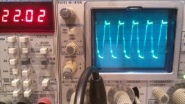
Looks great at 1khz, looks bad at 10khz. This is with the KT120's in it, which I'm waiting for a cool down then removing. 1khz was at a reading of 30vac on the meter and the 10khz was about 22vac, gets ugly as it approaches it.
Here are the pics for the KT120's, these are also biased a bit low at .060ma at 500v.
Edit : KT88 look similar, seems some ugly signals as the frequency goes up at power. Sine wave gets pointy at 10khz when you start driving it with 50watts+
Here are the pics for the KT120's, these are also biased a bit low at .060ma at 500v.
Edit : KT88 look similar, seems some ugly signals as the frequency goes up at power. Sine wave gets pointy at 10khz when you start driving it with 50watts+
Attachments
Last edited:
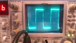
Use about 1/3 power for a square test. At 10k, it should look much cleaner. Also, phase compensation circuitry needs to be introduced to stop the ringing.
From the data you posted it looks like you may have stability issues. The square wave in my amps with heybor transformers looks almost flawless with my driver.
From the data you posted it looks like you may have stability issues. The square wave in my amps with heybor transformers looks almost flawless with my driver.
Attachments
SandyG,
In my post #43 I promised to have a look at the various load lines. I do however hesitate to continue; it will certainly not do to dump a lot of diverse suggestions on you by folks you do not know - or stuff you could very well have calculated for yourself.
Being thus cautious, may I nevertheless put forth the following results from analyses done by me:
The relatively low current through V6 (referring to one channel only) in the presence of an uninspiring load - some 60K in parallel with 47K, gave intuitive suspicion of a problem. Load line analysis shows that you may be running the cathodes 'into the ground' at about 80Vp signal, and at least incur noticable 2nd hrmonic distortion at the 50Vp odd signal required to drive KT88s.
Inspection shows that one can take R31, R37 down to 15K with advantage. The plate dissipation of each triode will then be 2,8W, still comfortably within the 3,75W allowed. R31-R37 will run at 2,5W each, necessitating wire-wounds for safety*. For a good operating point, to keep negative signal excursions well away from Ia=0, the cathode voltages need go to about 190V, bringing the plate voltages of the previous stage to some 184V. For this R29, R35 will have to go to 5,1K. R30, R35 can remain at 220K.
I was unable to do THD measurements; my analyser reposes on the shelf at present for repairs and I do not now have 6SN7s.
I also had a look at the seemingly unimpressive square wave response (only remember that any distortion at 10kHz will be at 20kHz and above; not audible.). Still, it would appear that you have two influences here: Some slight oscillation at about 90kHz, and a somewhat early loop gain attenuation at about 30kHz. R60-C30 does come in at about 50kHz, but not continuing the cut as a result of a relatively large R60.
But the feedback correcting capacitor C17 (over R19) only starts to act at 1MHz! You could thus first try to increase that to 200+pF; that compensation might lift the leading edge of the square wave. (Looking at a 5kHz square wave will more than suffice.) If you can get a 250 pF variable ceramic capacitor, and carefully mount it in place of C17, you could watch which position gives the 'squarist' response and build up from there. (Only keep hand and other stray capacity in mind.)
The remaining 80kHz wiggles I would associate with the output stage. You could experiment with the RCs from G2 - Anode. (Warning: High voltage!) Treat these two phenomena separately.
I hope these notes may be of value to you!
________________________________________________________
*Some make heavy weather of the inductance of wire-wound resistors in audio. That effect is generally so low as to be ignored. In fact, some induction might give a mite of h.f. compensation!
The drivers and the second gain stage of this amp is exactly the same of an Antique Sound Lab model 108 amplifier , that amp ( Antique ... ) with modifications sounds very good .
Yes, that amp and the Grommes 215 is were I got most of the circuits from.
SandyG,
In my post #43 I promised to have a look at the various load lines. I do however hesitate to continue; it will certainly not do to dump a lot of diverse suggestions on you by folks you do not know - or stuff you could very well have calculated for yourself.
Being thus cautious, may I nevertheless put forth the following results from analyses done by me:
The relatively low current through V6 (referring to one channel only) in the presence of an uninspiring load - some 60K in parallel with 47K, gave intuitive suspicion of a problem. Load line analysis shows that you may be running the cathodes 'into the ground' at about 80Vp signal, and at least incur noticable 2nd hrmonic distortion at the 50Vp odd signal required to drive KT88s.
Inspection shows that one can take R31, R37 down to 15K with advantage. The plate dissipation of each triode will then be 2,8W, still comfortably within the 3,75W allowed. R31-R37 will run at 2,5W each, necessitating wire-wounds for safety*. For a good operating point, to keep negative signal excursions well away from Ia=0, the cathode voltages need go to about 190V, bringing the plate voltages of the previous stage to some 184V. For this R29, R35 will have to go to 5,1K. R30, R35 can remain at 220K.
I was unable to do THD measurements; my analyser reposes on the shelf at present for repairs and I do not now have 6SN7s.
I also had a look at the seemingly unimpressive square wave response (only remember that any distortion at 10kHz will be at 20kHz and above; not audible.). Still, it would appear that you have two influences here: Some slight oscillation at about 90kHz, and a somewhat early loop gain attenuation at about 30kHz. R60-C30 does come in at about 50kHz, but not continuing the cut as a result of a relatively large R60.
But the feedback correcting capacitor C17 (over R19) only starts to act at 1MHz! You could thus first try to increase that to 200+pF; that compensation might lift the leading edge of the square wave. (Looking at a 5kHz square wave will more than suffice.) If you can get a 250 pF variable ceramic capacitor, and carefully mount it in place of C17, you could watch which position gives the 'squarist' response and build up from there. (Only keep hand and other stray capacity in mind.)
The remaining 80kHz wiggles I would associate with the output stage. You could experiment with the RCs from G2 - Anode. (Warning: High voltage!) Treat these two phenomena separately.
I hope these notes may be of value to you!
________________________________________________________
*Some make heavy weather of the inductance of wire-wound resistors in audio. That effect is generally so low as to be ignored. In fact, some induction might give a mite of h.f. compensation!
Johan -
Thanks so much for the detailed help!
It will take me a bit to understand them all.
One thing that I think is a bit problematic is the voltages to the 6SN7's, mainly the Cathode Follower since I think it is sitting right at the limit of Heater to Cathode for the 6SN7's. The Grommes 215A puts DC on the filaments and have that option but figured better to keep a safe levels. The Grommes also uses a bit different resistor set up for the Cathode follower and in retrospect I should have allowed for that in the circuit too.
To me, it also looks like the first stage (input) B+ is low in voltage, potentially a bit low in bias as 2.9v, but in looking at the 6SN7's curves at that voltage and 1.7ma it's in the lower end of the curve which I am guessing is not a good place for it, but the Grommes is also lower that I would expect.
For the compensation network C30-R60 I was not going to use that at all but will change that back to R60 of 27K where I think the Grommes Had it.
I may also small HV trimmer that could work for optimizing the feedback network.
Is it better to start with fixing voltages on the 6SN7 B+ then try some of the other changes?
Again, thank you for the very detailed help!
Sandy
Attachments
Last edited:
Use about 1/3 power for a square test. At 10k, it should look much cleaner. Also, phase compensation circuitry needs to be introduced to stop the ringing.
From the data you posted it looks like you may have stability issues. The square wave in my amps with heybor transformers looks almost flawless with my driver.
That looks a tad bit cleaner! I reduced the voltage a bit and it looks much cleaner but other things need to be adjusted a bit. I think some of the mentions by Johan are what you were saying also...
Sandy
- Status
- This old topic is closed. If you want to reopen this topic, contact a moderator using the "Report Post" button.
- Home
- Amplifiers
- Tubes / Valves
- EZ125 Quad KT88 Project