Hi Magz
I have my own pair of 833a (GU-48)home built monoblocks, but at the moment my HT is "only" 950v, and I drive the grid with a power interstage.
I am collecting more iron to rebuild the amps with higher HT, about 1300v as I don't need massive watts, and I may also follow your example and use Rod Coleman filament modules in parallel.
One question, the chokes you use on the raw DC supply are Hammond 159ZL ?
If so, does the 10A rating cause any problems ?
regards Philip.
Yes Philip, those are the chokes I used. I modified the ones that go in the first position with bolts through the frames to make them a little less prone to vibration, and mounted them on Deflex bushings. There is a description with pictures somewhere in this thread. They still do vibrate, however, but it's not audible from the listening position. If you have the room, go for 20A rated chokes in the L1 position. I didn't have enough room, so I made do.


Looking into options for a 20A 2.5mH choke, the Hammond 195E20 seems suitable, and the mains transformer could be an Antek 500va with two 20v secondaries, ref AN-5220. I have used Antek before and like their products.")
http://www.hammondmfg.com/pdf/5c0034.pdf
http://www.antekinc.com/an-5220-500va-20v-transformer/
http://www.hammondmfg.com/pdf/5c0034.pdf
http://www.antekinc.com/an-5220-500va-20v-transformer/
Last edited:
Magz,
Do you have detailed schematic for the whole PSUs in your amp? I recall you mentioned your B+ PSU is LCLC, but I didnt find details about the chokes. As I'm aware of, choke input filter demands quite a bit about the choke, both inductance and current capacity, especially when you are using very high voltage (2500VAC input), right?
Thanks,
Duong
Magz,
Do you have detailed schematic for the whole PSUs in your amp? I recall you mentioned your B+ PSU is LCLC, but I didnt find details about the chokes. As I'm aware of, choke input filter demands quite a bit about the choke, both inductance and current capacity, especially when you are using very high voltage (2500VAC input), right?
Thanks,
Duong
PSUDs are on page 5 and 6 of this thread. L1 needs to be a very good choke - for the 2500VAC I had Monolith make me a custom unit (35H). For the Driver I used a Lundahl choke. For the filament I used a Hammond (see above on this page).
Hi,
That is a great project and a great success. Congrats for that, Magz.
Though beeing involved with HiFi for many years and though the KR Kronzillas remain the best amps that ever drove my ESLs I had no closer connection with tubes.
Please allow for some basic Qs, related to the 833 but otherwise not ´Midlife crisis´ related.
Alas as ESLs and Tubes are meant to bond, there´s always been that nagging doubt that the double transformer interface between Tube and ESL should be omitted with.
Just out of ´I want it´ reason and not necesarily because of technically or sonic superiority .... which alone is very hard to beat.
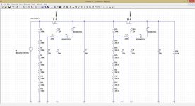
Attached is the basic sim file.
The model of the 833 seems to follow quite well the DS graphs and gave the expected (at least from me) results.
The circuit idea is as follows.
As input I´d like to use a audio transformer 1:1:1 to allow for balanced and unbalanced input, to achieve galvanic isolation against hum loops, and to achieve the required phase splitting, as a symmetrical ESL needs a pushpull drive.
The driver is modeled here as vcvs with a gain of appr. 25 times.
The DS graphs of the 833 indicate a plate current of ~90mA at a anode voltage of 1900V and a grid-cathode voltage of -35V.
If the grid is ground referenced a 390Ohm resistor would set the required bias points automatically.
As anode load I thought of using a choke, to achieve double the voltage swing.
I found the LL2743 anode choke by Lundahl, with following values:
Ibias: 90mA, Imax: 140mA, 50H, 400Ohm, 450Vrms(@30Hz).
Could a series connected sixpack of chokes suffice?
The values would be 300H, 2k4, 2700Vrms (capacitive load reduced to ~1/6)
Apart from the voltage drop due to the 2k4 copper resistance it seems well suited for the task.
It´d spare the hassle to have a specialized anode choke wound.
Up to +35Vpeak signal voltage (equalling ~25Vrms) there´d be no grid current and the output would be 1.78kVrms (pushpull).
The KR Kronzilla driving through the 1:50 step up transformer gives 1,2kVrms, which is already close to the limit of the panel (its a highly efficient panel, playing at appr. 105dB@4m at this voltage level).
The triode would limit at around +-50Vpp input, the last +15V signal overhead requiring up to 20mA grid current, which is the point the tube glides into A2 mode and THD rises.
For lab experiments I could use any power amplifier of the 100W/8Ohm class as it could supply for 28Vrms grid signal.
So far it seems that the 833 presents just the right set of parameters for a simple to drive ground referenced grid, cathode resistor biased Tube stage.
Would it also be possible to replace the anode chokes and output coupling caps by a pushpull transformer 10k:8:4Ohms directly?
After the sim this should give around 80W of power, without changing anything els in the ircuit.
If it has been too offtopic just delete the post.
jauu
Calvin
That is a great project and a great success. Congrats for that, Magz.
Though beeing involved with HiFi for many years and though the KR Kronzillas remain the best amps that ever drove my ESLs I had no closer connection with tubes.
Please allow for some basic Qs, related to the 833 but otherwise not ´Midlife crisis´ related.
Alas as ESLs and Tubes are meant to bond, there´s always been that nagging doubt that the double transformer interface between Tube and ESL should be omitted with.
Just out of ´I want it´ reason and not necesarily because of technically or sonic superiority .... which alone is very hard to beat.
Attached is the basic sim file.
The model of the 833 seems to follow quite well the DS graphs and gave the expected (at least from me) results.
The circuit idea is as follows.
As input I´d like to use a audio transformer 1:1:1 to allow for balanced and unbalanced input, to achieve galvanic isolation against hum loops, and to achieve the required phase splitting, as a symmetrical ESL needs a pushpull drive.
The driver is modeled here as vcvs with a gain of appr. 25 times.
The DS graphs of the 833 indicate a plate current of ~90mA at a anode voltage of 1900V and a grid-cathode voltage of -35V.
If the grid is ground referenced a 390Ohm resistor would set the required bias points automatically.
As anode load I thought of using a choke, to achieve double the voltage swing.
I found the LL2743 anode choke by Lundahl, with following values:
Ibias: 90mA, Imax: 140mA, 50H, 400Ohm, 450Vrms(@30Hz).
Could a series connected sixpack of chokes suffice?
The values would be 300H, 2k4, 2700Vrms (capacitive load reduced to ~1/6)
Apart from the voltage drop due to the 2k4 copper resistance it seems well suited for the task.
It´d spare the hassle to have a specialized anode choke wound.
Up to +35Vpeak signal voltage (equalling ~25Vrms) there´d be no grid current and the output would be 1.78kVrms (pushpull).
The KR Kronzilla driving through the 1:50 step up transformer gives 1,2kVrms, which is already close to the limit of the panel (its a highly efficient panel, playing at appr. 105dB@4m at this voltage level).
The triode would limit at around +-50Vpp input, the last +15V signal overhead requiring up to 20mA grid current, which is the point the tube glides into A2 mode and THD rises.
For lab experiments I could use any power amplifier of the 100W/8Ohm class as it could supply for 28Vrms grid signal.
So far it seems that the 833 presents just the right set of parameters for a simple to drive ground referenced grid, cathode resistor biased Tube stage.
Would it also be possible to replace the anode chokes and output coupling caps by a pushpull transformer 10k:8:4Ohms directly?
After the sim this should give around 80W of power, without changing anything els in the ircuit.
If it has been too offtopic just delete the post.
jauu
Calvin
Attachments
why not a cascaded mosfet (IXTF1N400) stage for the HV?
HV transformer 2692Vrms + Bridge (4x 8xC3D10170H+2M0/RNX075-0µ01/3000VDC/MKP10) + capacitor (series of 8x 260µ/MKP5+bleeder resistors) + electronic choke for 2300VDC@200mA.
Sure, I guess one could do that. Right now the amps sound so good I'm not touching them, though; I can't imagine being more pleased. I've moved on to shoehorning a DAC into my 26 preamp as my winter project for this year.
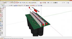
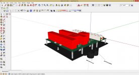
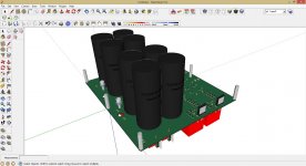
... the high voltage PCB placement finished. Switching to the driver stage.
The PCB is 4 layers (FR4 --> 10kV/mm); faston 6.3mm for the microwave ofen fuse onboard; no electrolyt, M3 faston for central ground and high voltage for the OT.
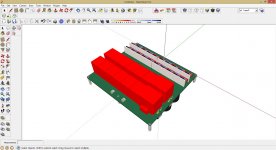
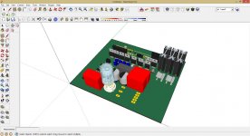
... the components for the driver stage (last post to clarify the wiring of the MOSFET voltage reference)...
The PCB is 4 layers (FR4 --> 10kV/mm); faston 6.3mm for the microwave ofen fuse onboard; no electrolyt, M3 faston for central ground and high voltage for the OT.
... the components for the driver stage (last post to clarify the wiring of the MOSFET voltage reference)...
Attachments
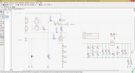
is this correct (V8, V9, R43 and R42)?
If you're asking me...
I didn't use R42, just a grid choke with no additional resistor (it's optional).
I strapped the 6E5P screen grid to the plate using a 200R resistor plus a
UF4007 diode (cathode away from the plate).
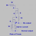
I'm not sure what you're doing with that Vref...it should be a cascoded CCS set to few mA, feeding a resistor, with an adjustment pot. The only connection to the driver circuit is to the gate of the AOT2N60 (from the point between the pot and the resistor).
.
Last edited:
CCS looks like the attached. Connect a suitable V source to the top, add the resistor at the bottom (where it says "Plate of Triode") and connect the "Normal output" to the circuit in my schematic in post #1, where V7 is connected. If you want 216V, and use a 47k resistor, you'll want the CCS set to about 4.6mA. You can then adjust the current through the CCS using the pot to get the voltage you want on the gate of the AOT2N60.
Attachments
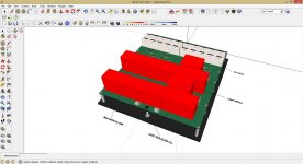
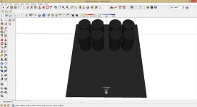
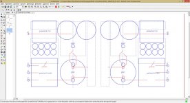
... preliminary left and right symetrical placement...
Nice and symmetrical, but I'd try to get the signal as far away from the power supply as possible. In my amps the PS is in the back of the amps and all the signal wires are in the front 25%. Layout is key; the noise floor in my amps is 300uV, without using any shielded wires for the signal.
many thanks Magz!
Kevin from K&K gives me the schematics for the V3 shunt regulator with the DN2540 and LM334 improvement.
I will update my schematics tomorrow...
My own thread after GM-70, 211 and DAC (I am waiting for the OT and the 3D parts).
But if Santa Claus is very generously (6000€ for the copper for stereo 833C)...
The aim should be a 833C GB?! But I need help to manage this monster project.
But first, get a good base with the schematics...
Magz: I´m very interested about the temperature in the case
- Home
- Amplifiers
- Tubes / Valves
- The Midlife Crisis - My 833C Amp Build