The 12AU7 is not linear. So, steer clear. The "classic" tube for Williamson style small signal circuitry is the 6SN7. You can save some real estate by using the electrically equivalent 6FQ7/6CG7.
Williamson style topology requires premium O/P transformers and careful adjustment of the high pass filter 1/2 power points. Failure to observe the appropriate precautions ends in low frequency instability.
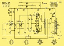
When working with O/P "iron" that's less than stellar, Mullard 5-20 style small signal topology is (IMO) a better choice. Dodging the low freq. instability bullet is much easier, when Mullard style small signal topology is used. One of the finest implementations of Mulllard style circuitry is the Harman/Kardon Citation V.
Williamson style topology requires premium O/P transformers and careful adjustment of the high pass filter 1/2 power points. Failure to observe the appropriate precautions ends in low frequency instability.
When working with O/P "iron" that's less than stellar, Mullard 5-20 style small signal topology is (IMO) a better choice. Dodging the low freq. instability bullet is much easier, when Mullard style small signal topology is used. One of the finest implementations of Mulllard style circuitry is the Harman/Kardon Citation V.
Attachments
Isn't that a long tailed pair?
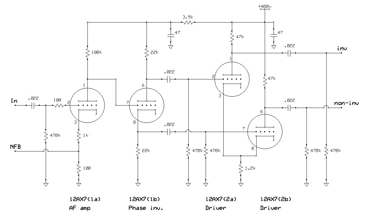
The hallmarks of Mullard style circuitry are a voltage gain block DC coupled to a differential phase splitter (LTP).
Careful examination will reveal the same number of high pass poles as found in Williamson style circuitry. However, it's very easy to get the pole associated with the non-inverting grid to have a F3 quite close to zero Hz. That avoids the low freq. instability problem. Slipshod work on a Williamson setup yields a phase shift oscillator. It's much harder to make that mistake, when a Mullard setup is employed. A key factor that must be taken into account is the phase shift introduced by the O/P transformer.
When people refer to the "mullard setup" are they always referring to a ltp or is their something specific about the mullard?
Does the problem of opt induced phase shift increase as nfb is increased?
Here's the datasheet. Does that shed any light on it's use? Doesn't seem to be very high gain either.
http://datasheets.hypertriton.com/12BY7A.pdf
http://datasheets.hypertriton.com/12BY7A.pdf
Thanks, lazzer. I did some poking around, curious about this and still learning stuff ")
Looks like the designs are operating the pentode in a kind of UL mode with the bias and feedback. Interesting, and complicated - but that's why the HK amps are so spendy, I guess!
Never too old to teach a late-dog new tricks
~ Sam
EDIT - HK... "Harmon-Kardon", not "Hong-Kong"
EDIT - lazzer, here's a tutorial on the thing. http://ampbooks.com/home/tutorials/pentode-tutorial-1/
Oops, looks I've embedded an errant-smiley into this post, dunno how to get rid of it (can't see it in the edit or attachments) Don't bother to click on the link, nothing there anyway...
Last edited:
Sh*t! I lost a lot of typing.
The 12BY7 is actually a high gain device. The parameter to look at in pentodes is transconductance (gm). When "constant" current arrangements, like pentodes and cascodes, are in use, a Norton equivalent circuit, as opposed to the Thevenin equivalent circuit used with triodes, is convenient. Stage gain is approximately gm X net load impedance.
The voltage amplifier at the I/P of both the Mullard and Williamson setups introduces a 180o phase shift. When the phase shifts of RC poles and the O/P trafo add up to 180o too, the feedback is positive, not negative. Barkhausen's criterion is satisfied and oscillation begins.
Sh*t! I lost a lot of typing.
The 12BY7 is actually a high gain device. The parameter to look at in pentodes is transconductance (gm). When "constant" current arrangements, like pentodes and cascodes, are in use, a Norton equivalent circuit, as opposed to the Thevenin equivalent circuit used with triodes, is convenient. Stage gain is approximately gm X net load impedance.
The voltage amplifier at the I/P of both the Mullard and Williamson setups introduces a 180o phase shift. When the phase shifts of RC poles and the O/P trafo add up to 180o too, the feedback is positive, not negative. Barkhausen's criterion is satisfied and oscillation begins.
There's a gremlin in this thread, Eli! (Or should we just blame Bill G like for everything else ebil in life
)Don't want to hijack this thread, either - many thanks for sharing your observations on this circuit, tho'. I will go look for a pentode-preamp thread - it looks like an interesting subject that is perhaps overlooked a bit since most of the designs I see here use "standard" triode inputs.
This application seems to be more in line with instrument amplifier needs, where higher gain in the preamp and driving a tone-stack are usually required. Not so much the case with our Hi-Fi applications, where typically we have relatively high input signals and are most certainly not driving a tone-stack! (although I suppose a phono-input might have the higher-gain requirement.)
Thanks for the feedback, Eli
!"My amplifier oscillates, my oscillator won't" - lament of the radio engineer...
~ Sam
Last edited:
Sh*t! I lost a lot of typing.
The 12BY7 is actually a high gain device. The parameter to look at in pentodes is transconductance (gm). When "constant" current arrangements, like pentodes and cascodes, are in use, a Norton equivalent circuit, as opposed to the Thevenin equivalent circuit used with triodes, is convenient. Stage gain is approximately gm X net load impedance.
The voltage amplifier at the I/P of both the Mullard and Williamson setups introduces a 180o phase shift. When the phase shifts of RC poles and the O/P trafo add up to 180o too, the feedback is positive, not negative. Barkhausen's criterion is satisfied and oscillation begins.
Now you lost me. I'll just reverse the secondary and go back to negative feedback.
To me, the Williamson design makes sense. From what I've read, the cathodyne PI has unequal impedance (or capacitance?) between the two phases. With a driver stage following the cathodyne, can't we keep the effects of imbalance to a minimum?
As far as the gain on the input pentode... We're only talking about voltage gain correct? When the tone stack was mentioned it sparked thoughts about how the pentode may be better suited to drive current for a tone stack.
What was the application of the two schematics that were posted? PA systems by chance? I had a tubed Bogen PA amp that, I think, used a pentode preamp. Were they designed for microphones on the input?
Last edited:
The 2 Mullard circuit examples I uploaded are very serious HIFI designs.
Dig around in the archives. You'll find all sorts of info. debunking myths about split load, AKA "cathodyne", AKA "concertina", phase splitters. In a nutshell, a properly set up "concertina" splitter is nearly perfect. The legitimate complaint about the "concertina" is poor voltage swing capability. Williamson dealt with that issue by incorporating a differential gain block between the splitter and the "finals".
Dig around in the archives. You'll find all sorts of info. debunking myths about split load, AKA "cathodyne", AKA "concertina", phase splitters. In a nutshell, a properly set up "concertina" splitter is nearly perfect. The legitimate complaint about the "concertina" is poor voltage swing capability. Williamson dealt with that issue by incorporating a differential gain block between the splitter and the "finals".
How does one choose an output transformer? I know it has to do with the b+ voltage and output tubes. How are the variables written into equation to calculate the primary impedance? (will google this info in a moment). Say I ran 450v b+ with 4 6L6s (per-channel) with an 8 ohm speaker, how do I determine the OPT?
I'm fiddling with Williamson's design. I like the idea of making a universal driver PCB since the topology itself is fairly simple. I'm sure there's more to do but this is my starting point.
I'm fiddling with Williamson's design. I like the idea of making a universal driver PCB since the topology itself is fairly simple. I'm sure there's more to do but this is my starting point.
Attachments
Last edited:
The 12AX7 is an absolute no/no!! It provides EXCESSIVE gain and wretched drive capability. Williamson knew what he was doing in selecting the highly linear 6SN7. Stick to that type or its very close relatives. Among its many good points, the 6SN7 contains reasonably high gm triodes. High gm protects against HF error correction signal induced slew limiting, in designs that incorporate loop NFB.
The 12AU7 is NOT a Noval equivalent of the 6SN7. The Noval type you want is the 6FQ7/6CG7.
People use the 12AU7 because it draws 300 mA. of heater current, while the 6FQ7, like the 6SN7, draws 600 mA. of heater current. The 12AU7 has linearity problems and (IMO) should be restricted to cathode follower and "concertina" phase splitter service, in serious HIFI designs. Local current NFB, inside the tube, disposes of the linearity concerns, in those specific situations.
People use the 12AU7 because it draws 300 mA. of heater current, while the 6FQ7, like the 6SN7, draws 600 mA. of heater current. The 12AU7 has linearity problems and (IMO) should be restricted to cathode follower and "concertina" phase splitter service, in serious HIFI designs. Local current NFB, inside the tube, disposes of the linearity concerns, in those specific situations.
Mosquito, are you still buzzing around the thread? Would it be a bother to emulate the schematic above and see how it performs?
I found some 6SN7s but they don't match. They look completely different. One is a GE and the other a Silvertone. I found some 6SN7s coke bottles that look pretty cool. http://www.sophiaelectric.com/pages/se/6sn7.htm
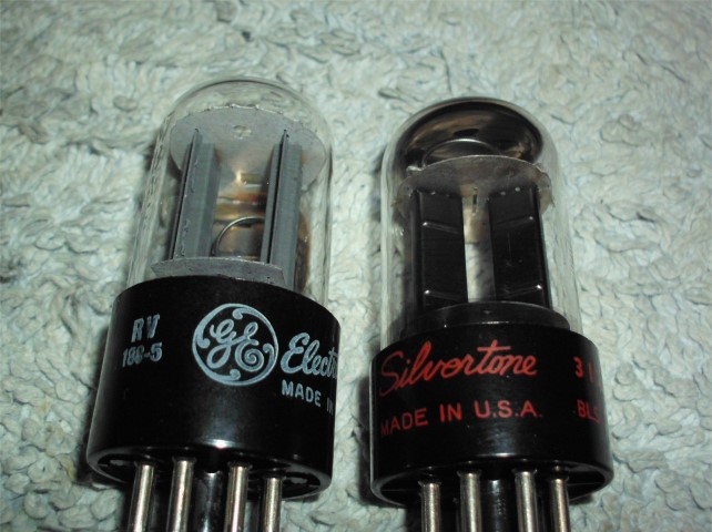
I found some 6SN7s but they don't match. They look completely different. One is a GE and the other a Silvertone. I found some 6SN7s coke bottles that look pretty cool. http://www.sophiaelectric.com/pages/se/6sn7.htm
Attachments
Last edited:
The 12AU7 is NOT a Noval equivalent of the 6SN7. The Noval type you want is the 6FQ7/6CG7.
People use the 12AU7 because it draws 300 mA. of heater current, while the 6FQ7, like the 6SN7, draws 600 mA. of heater current. The 12AU7 has linearity problems and (IMO) should be restricted to cathode follower and "concertina" phase splitter service, in serious HIFI designs. Local current NFB, inside the tube, disposes of the linearity concerns, in those specific situations.
Eli, I read a very good article about the Williamson amp that helped me understand a few things that had me stumped. The writer suggested using 12AU7s as the drivers (plate followers) because the 6SN7 has much high capacitance. In his revision, he paralleled the 12AU7's triodes. His complete preamp/PI/driver stage consisted of a 6SN7 as preamp/cathodyne and 2 12AU7s (with their triodes paralleled) as drivers. I'll try and find the article again.
Opinions?
EDIT - Here's the article. There are a few errors in the schematics.
Last edited:
If he uses 12AU7s as voltage amplifiers, which is what the drivers in a Williamson setup are, I am inclined to view his work with GREAT suspicion. The fundamental non-linearity of the 12AU7 will not go away. If somebody is worried about driver tube plate resistance and O/P tube Miller capacitance interacting adversely, the ECC99 is (IMO) the tube to use in place of the 6SN7. Notice the low RP, high gm, and μ of 22. The plate curves look pretty good too. The ECC99 is, indeed, a superior driver and you need only 1 bottle per channel.
The plate curves look pretty good too. The ECC99 is, indeed, a superior driver and you need only 1 bottle per channel.The ECC99 is NOT the same as the 12BH7. Check the data sheets out.
There's no good reason to switch from the 6SN7/6FQ7/7N7 group as the preamp/splitter, in a Williamson setup. The triode in those bottles is as linear as they come and stress levels are low. Also, you can't ignore the 800 mA. heater draw of an ECC99.
There's no good reason to switch from the 6SN7/6FQ7/7N7 group as the preamp/splitter, in a Williamson setup. The triode in those bottles is as linear as they come and stress levels are low. Also, you can't ignore the 800 mA. heater draw of an ECC99.
- Status
- This old topic is closed. If you want to reopen this topic, contact a moderator using the "Report Post" button.
- Home
- Amplifiers
- Tubes / Valves
- Found myself a Magnavox 9302-00