You can try it yourself. Here is the spice model I created for the pair of 3A5 triodes in parallel:
http://www.bartola.co.uk/valves/2013/01/19/3a5-dht-continued/
Don't want to be the bearer of bad news, but 3A5 is better suited for low signal (e.g. Preamps, etc.)
Ale
http://www.bartola.co.uk/valves/2013/01/19/3a5-dht-continued/
Don't want to be the bearer of bad news, but 3A5 is better suited for low signal (e.g. Preamps, etc.)
Ale
I'm in agreement with Ale on this one. I've considered 3A5 for a long time for input duty, and it's excellent as long as you don't feed it too much swing. Plus, I don't see anything wrong with driving the 4P1L output with a triode connected 4P1L. Should work for most headphones at volumes that your ears will be sore. Different story for a power amp. Pano, which headphones exactly are you planning to use?
Used as input in a 3 stage amp should be fine otherwise I tried to say this implicitly some posts ago talking about the ECC40.I found 3A5 not that linear when swinging lots of voltages, good for low level signals though.
How many volts are you looking the 3A5 to swing?
Ale
The 3a5 is a very decent sounding DHT but not a great one. Another similar mu one is the 1J6 - it has a fuller and meatier sound. The sections are not usually too well balanced, however. It can sound good. But not in the class of the 26 and 4P1L to my ears. I've used all these.
Two stages, both with 4P1L would be just fine IMHO.
Pano says it has a gain of 10. IMO that is quite high for the very efficient Sennheisers. For reference I have a Beta22 here with voltage gain of 6, and with my 2vrms output DAC I am rarely past 10 o'clock on the volume.
I'm using Pete Millet's calculator to gauge output levels. It doesn't seem like I will need more than 300 mw of output, I'm trying to keep the transformers as small as possible and considering using custom wound Electra-Print or Sowter.
Last edited:
Sennheiser HD580. Nominally 300 ohms. I can drive them to quite satisfactory levels with a 25:1 OPT terminated with 8 ohms and the headphones. They won't knock your ears off, but for most materials it's plenty loud.dphones at volumes that your ears will be sore. Different story for a power amp. Pano, which headphones exactly are you planning to use?
Some of my lower impedance cans, like JVC, don't get as loud at the same setting.
Sennheiser HD580. Nominally 300 ohms. I can drive them to quite satisfactory levels with a 25:1 OPT terminated with 8 ohms and the headphones. They won't knock your ears off, but for most materials it's plenty loud.
Some of my lower impedance cans, like JVC, don't get as loud at the same setting.
Why 8 Ohm? If you load secondary on higher load resistance the load line will go more horizontally. As the result, you will get slightly higher output voltage, and much lower distortions. However, load resistance should be reasonable so the transformer would not be damaged in case of saturation. I think something like 33-56 Ohm load resistor would be just fine.
Yes. I was just using an 8 ohm dummy load in this case to mimic speakers. I'll try with a higher load.
EDIT: A 40R load brings the output voltage up by 50%. A nice improvement.
In fact I measured again and I was wrong about the gain. Looks like a voltage gain of about 7 in each stage - at the least the way that it's now running.
EDIT: A 40R load brings the output voltage up by 50%. A nice improvement.
In fact I measured again and I was wrong about the gain. Looks like a voltage gain of about 7 in each stage - at the least the way that it's now running.
The 3a5 is a very decent sounding DHT but not a great one. Another similar mu one is the 1J6 - it has a fuller and meatier sound. The sections are not usually too well balanced, however. It can sound good. But not in the class of the 26 and 4P1L to my ears. I've used all these.
IJ6 only has a gain of 8.
I think to drive the 4P1l to the output we need the 3A5 makes the most since with its gain of 15 and current of ~10mA.
I'm sure folks are thinking they can use something like a cap couple 2 stage 26-4p1l or even 4p1l-4p1l, but ask yourself why not just build a SPUD amp if that's all the power you need. It will be an OK amplifier, about the same power as the schematic from the mid 2000's shown on the first page.
If you are after excellent linearity and don't need much power then a 6c45p1/WE437 SET spud amp is the best route to take. It will power most headphones with distortion below -70db.
But to take advantage of the DHT output to allow a larger compatibility with different headphones, I think we need the 3A5 on the input and probably a little mic step-up transformer or rod's shunt circuit.
I'm in agreement with Ale on this one. I've considered 3A5 for a long time for input duty, and it's excellent as long as you don't feed it too much swing. Plus, I don't see anything wrong with driving the 4P1L output with a triode connected 4P1L. Should work for most headphones at volumes that your ears will be sore. Different story for a power amp. Pano, which headphones exactly are you planning to use?
Looking at the 3A5 curves, would need to run it around 140V plate -5Vgrid, I can see how the 3A5 may have a bad rap swing large voltage if it isn't biased to keep the grid away from 0.
Looking at the 3A5 curves, would need to run it around 140V plate -5Vgrid, I can see how the 3A5 may have a bad rap swing large voltage if it isn't biased to keep the grid away from 0.
That quiescent point is above the maximum Pa: 15ma and 140V for paralleled triodes. I tried many quiescent points and got disappointed with any performance above 5Vrms output. Agree with keeping the grid away from 0, but is not enough in this valve unless you want to run it a very low current.
Do your own tests before rushing to a conclusion about this valve
")
Ale
I have the 1J6G down as a mu of 14. Anode resistance 10K, S=1.4. I'm not sure where I got S=1.4 from. A post on AA gives mu as 20. Kurt Strain says "I don't know for sure anymore, but 14 sounds about right to me, too. These are nice sounding, but a bit warm and fuzzy for a DHT, after looking into other DHT's out there. Very easy filament to heat, though, not a lot of current. They were designed for battery operated class B output stages drawing low power."
I may have got it from Piotr Grzesik who used it as a driver. "Mu is indeed *about* 14, but it's hard to be accurate as there's no class-A data about. I just extrapolated the class-B data."
I found it about the same in audio quality as a 3a5, but a fuller sound. It's a possibility, though I wouldn't push it too hard.
the curves for the 1J6G on Frank's website show about 8mu.
As far as the 3a5-4P1l vs the 4p1l (dc-coupled), according to ltspice they both have about the same Pmax (about 1 watt) into 38 ohms at 5% THD (A1 +6V grid). But the 3A5 has much better input sensitivity. I am accounting for transformer losses, capacitance, etc (it adds up.)
If I decide on 4p1l to 4p1L I would want a small 1:2 step-up up transformer at the input, this would be good for those with balanced sources also. My concern is some masterings are -6dB which and I would run out of volume without a pre-amp.
4П1Л stage can achieve much more gain with shunt cascode arrangement. This works even better if you like dc-coupling, and want to remove all the coupling capacitors.
shunt cascode removes the power supply cap from the signal path, too, since there is no signal current in the power supply with this circuit.
All that remains is to remove the input cap. That's easy - filament bias works especially well with 4П1Л.
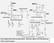
here's an example circuit, to assemble all these features. Filament bias in the first stage, shunt cascoded to give a gain of 35. the output stage has the automatic cathode bias circuit - with dynamic impedance reduced to a few ohms, to allow full gain from the output 4П1Л.
No negative supply needed either - just a single 280V rail.
As an alternative to the cathode bias controller, we can just use filament bias for both stages, and couple using Russian teflon 100nF.
The whole circuit can give the 38 ohm headphones a pk-pk output of 18V, for 400mV pk-pk in.
shunt cascode removes the power supply cap from the signal path, too, since there is no signal current in the power supply with this circuit.
All that remains is to remove the input cap. That's easy - filament bias works especially well with 4П1Л.
here's an example circuit, to assemble all these features. Filament bias in the first stage, shunt cascoded to give a gain of 35. the output stage has the automatic cathode bias circuit - with dynamic impedance reduced to a few ohms, to allow full gain from the output 4П1Л.
No negative supply needed either - just a single 280V rail.
As an alternative to the cathode bias controller, we can just use filament bias for both stages, and couple using Russian teflon 100nF.
The whole circuit can give the 38 ohm headphones a pk-pk output of 18V, for 400mV pk-pk in.
Attachments
What about this Russian DHT:2Ж27Л / 2SH27L / 2Z27L. It was also designed for battery operation, it's very cheap and has a mu of 16.
Heater voltage: 2.2V
Heater current: 57mA
Anode voltage: 120V (200V maximum)
Anode current 1.9mA (2.5mA maximum)
Transconductance: 1.9mA/V
I did some test prior to Christmas, traced curves and even produced an SPICE model. Found that is good for small signal, but again biased at about -4V linearity is not that great. I'm sure a better quiescent point can be found:
2?27? / 2SH27L / 2Z27L | Bartola Valves
I haven't tested how this one sounds, but its worth considering perhaps as first stage...
Ale
4П1Л stage can achieve much more gain with shunt cascode arrangement. This works even better if you like dc-coupling, and want to remove all the coupling capacitors.
shunt cascode removes the power supply cap from the signal path, too, since there is no signal current in the power supply with this circuit.
All that remains is to remove the input cap. That's easy - filament bias works especially well with 4П1Л.
here's an example circuit, to assemble all these features. Filament bias in the first stage, shunt cascoded to give a gain of 35. the output stage has the automatic cathode bias circuit - with dynamic impedance reduced to a few ohms, to allow full gain from the output 4П1Л.
No negative supply needed either - just a single 280V rail.
As an alternative to the cathode bias controller, we can just use filament bias for both stages, and couple using Russian teflon 100nF.
The whole circuit can give the 38 ohm headphones a pk-pk output of 18V, for 400mV pk-pk in.
I could use this for another thing...more exciting for me!
What are you using as primary load in the OPT? 5K?
- Home
- Amplifiers
- Tubes / Valves
- The all DHT SET Headphone Amp