I could use this for another thing...more exciting for me!
What are you using as primary load in the OPT? 5K?
Yes, I assumed 12:1 for the transformer turns-ratio, so about 5400 ohms.
The shunt cascode circuit is well-proven - I use 3 stages of this circuit to get from MC (Denon DL103) to 300B grid!
4П1Л stage can achieve much more gain with shunt cascode arrangement. This works even better if you like dc-coupling, and want to remove all the coupling capacitors.
shunt cascode removes the power supply cap from the signal path, too, since there is no signal current in the power supply with this circuit.
All that remains is to remove the input cap. That's easy - filament bias works especially well with 4П1Л.
here's an example circuit, to assemble all these features. Filament bias in the first stage, shunt cascoded to give a gain of 35. the output stage has the automatic cathode bias circuit - with dynamic impedance reduced to a few ohms, to allow full gain from the output 4П1Л.
No negative supply needed either - just a single 280V rail.
As an alternative to the cathode bias controller, we can just use filament bias for both stages, and couple using Russian teflon 100nF.
The whole circuit can give the 38 ohm headphones a pk-pk output of 18V, for 400mV pk-pk in.
I assume, you wanted 249.4V Vcascode, instead of 250.6V. And even if you set it precise, and well stabilized, output tube will see very random and dependent on weather in Zimbabwe bias voltage. And if your servo in cathode of an output stage will somehow compensate it, anode current of the first stage tube will depend on Amazon rainforests.
Last edited:
I assume, you wanted 249.4V Vcascode, instead of 250.6V. And even if you set it precise, and well stabilized, output tube will see very random and dependent on weather in Zimbabwe bias voltage. And if your servo in cathode of an output stage will somehow compensate it, anode current of the first stage tube will depend on Amazon rainforests.
hi Anatoliy,
That's OK. The dc level of the driver output, nor the supply voltage of the driver (nor the output stage) are not precisely specified.
The servo sets the output stage current, regardless of any of the voltages - within reason.
The cascode voltage should be regulated for best performance - not for dc reasons, but because we prefer low impedance drive of the base voltage.
Seems like a nice circuit, but I honestly don't like to use a bjt for amplification in an "all DHT" amplifier. This being said, I have not built it, so I have absolutely no idea how it would sound.
It's OK - we are not using the BJT for amplification.
Its job is simply to fix the anode voltage of the triode, and steer the triode's current variations into the load resistor.
The sound of it surpasses the usual triode stages easily, and often you can replace 2 stages of triodes with one shunt cascode.
Comparing the sound of shunt cascode (eg EF80 triode) driving 300B to the often-seen 2-stage 6SN7 is very revealing.
Yes, I assumed 12:1 for the transformer turns-ratio, so about 5400 ohms.
The shunt cascode circuit is well-proven - I use 3 stages of this circuit to get from MC (Denon DL103) to 300B grid!
I would like to try with the 45 PP to get 17W. The bias of the output stage is the same for the 5.5W class A amplifier and the 17W class AB2 amplifier (i.e. 275V/36 mA and 3.9K). Only difference is the drive. The OPT in your design is replaced by a SE-to-PP interstage like the Lundahl LL1660 or LL1692A.
Last edited:
I would like to try with the 45 PP to get 17W. The bias of the output stage is the same for the 5.5W class A amplifier and the 17W class AB2 amplifier (i.e. 275V/36 mA and 3.9K). Only difference is the drive. The OPT in your design is replaced by a SE-to-PP interstage like the Lundahl LL1660 or LL1692A.
A 4p1L differential pair driver dc coupled
") nice. A bit off topic but worth analysing it....
nice. A bit off topic but worth analysing it....It's OK - we are not using the BJT for amplification.
Its job is simply to fix the anode voltage of the triode, and steer the triode's current variations into the load resistor.
The sound of it surpasses the usual triode stages easily, and often you can replace 2 stages of triodes with one shunt cascode.
Comparing the sound of shunt cascode (eg EF80 triode) driving 300B to the often-seen 2-stage 6SN7 is very revealing.
Despite of CCS anode current supply, load line of the triode is almost vertical. And "steering" is not linear, since collector current is the sum of emitter and base currents. Base current is not linear.
I would like to try with the 45 PP to get 17W. The bias of the output stage is the same for the 5.5W class A amplifier and the 17W class AB2 amplifier (i.e. 275V/36 mA and 3.9K). Only difference is the drive. The OPT in your design is replaced by a SE-to-PP interstage like the Lundahl LL1660 or LL1692A.
Yes, this could be interesting. Maybe worth a new thread?
For the interstage maybe Sowter 8423 also worth a look -
INTERSTAGE TRANSFORMERS FOR VALVE TUBE AMPLIFIERS
Despite of CCS anode current supply, load line of the triode is almost vertical.
That's correct. This is intentional! Many triodes, and triode-connected pentodes work excellently this way.
And "steering" is not linear, since collector current is the sum of emitter and base currents. Base current is not linear.
Not quite correct. Collector current is the **difference** of the emitter and base currents. And if Darlington connexion is adopted, almost all base current can be returned to the output - making the difference extremely small.
Or, we can use PMOS device to eliminate it.
When you consider -
- the high gain (frequently good enough to replace 2 triode stages)
- no signal current in power supply
- input and output both referred to ground
- very high power supply rejection
- easily adapted to dc coupling
it becomes clear how useful this architecture is.
Yes the Sowter is good as well.Yes, this could be interesting. Maybe worth a new thread?
For the interstage maybe Sowter 8423 also worth a look -
INTERSTAGE TRANSFORMERS FOR VALVE TUBE AMPLIFIERS
I will send you a pm, sooner or later, if you don't mind.
End of OT.
Last edited:
Pardon, mistyping. Of course collector current is the difference, but base current depends on collector current non-linearly. Look at curves of dependence of beta on collector current.
Rod, I would never use such "steering" without negative feedback, and I would suggest you to close servo loop through the 1'st anode current source. Such a way you will keep all together under control.
Try it in non-virtual reality and see what I mean.
Rod, I would never use such "steering" without negative feedback, and I would suggest you to close servo loop through the 1'st anode current source. Such a way you will keep all together under control.
Try it in non-virtual reality and see what I mean.
Pardon, mistyping. Of course collector current is the difference, but base current depends on collector current non-linearly. Look at curves of dependence of beta on collector current.
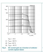
Please see the Hfe characteristic of the 500V PBHV9040Z. This excellent new NXP transistor has effectively constant Hfe across the full range of current required in our driver applications.
http://www.nxp.com/documents/data_sheet/PBHV9040Z.pdf
And with darlington connexion, the base current error is almost totally removed.
Rod, I would never use such "steering" without negative feedback, and I would suggest you to close servo loop through the 1'st anode current source. Such a way you will keep all together under control.
Try it in non-virtual reality and see what I mean.
It's OK - I have tried it for the last 8 years in the driver for my 300B, completely open-loop. Very real reality!
Still, I agree that dc-stabilisation of the current source (or the triode bias) might be useful, and have been considering circuits for this.
Attachments
Yes the Sowter is good as well.
I will send you a pm, sooner or later, if you don't mind.
End of OT.
A new thread is worth starting as many of us are interested in this topology for an amp including PP
It's OK - we are not using the BJT for amplification.
Its job is simply to fix the anode voltage of the triode, and steer the triode's current variations into the load resistor.
The sound of it surpasses the usual triode stages easily, and often you can replace 2 stages of triodes with one shunt cascode.
Comparing the sound of shunt cascode (eg EF80 triode) driving 300B to the often-seen 2-stage 6SN7 is very revealing.
About the sound I cannot say anything. But I cannot agree that the 2N5401 in the circuit you posted is not used in amplification. From a 4P1L you can get about 20dB gain, max. The gain at the collector of the bjt is about 30dB. If the bjt doesn't amplify you have to ask yourself where the extra 10dB is coming from? The output stage can be safely left out.
About the sound I cannot say anything. But I cannot agree that the 2N5401 in the circuit you posted is not used in amplification. From a 4P1L you can get about 20dB gain, max. The gain at the collector of the bjt is about 30dB. If the bjt doesn't amplify you have to ask yourself where the extra 10dB is coming from? The output stage can be safely left out.
4P1L in his device has current output driving emitter of the "common base" BJT stage that is loaded on resistor. Both devices amplify the signal. However, if Rod likes the sound of his setup, and is satisfied by it's stability of parameters, it is his choice. But as I said, I would stabilize DC parameters of all directly - coupled thingy together, and definitely would add negative feedback around it. Religious people then would have a chance to compare and decide, which one is better according to their religion, by sound only, without knowing what ius inside.
4P1L in his device has current output driving emitter of the "common base" BJT stage that is loaded on resistor. Both devices amplify the signal.
Seems to me it's a classic transimpedance amplifier.
However, if Rod likes the sound of his setup, and is satisfied by it's stability of parameters, it is his choice.
I completely agree. I was just pointing out that it's not a two stage amplifier, rather it has three stages, the first two being formed by two DC coupled active devices: a tube and a bjt.
- Home
- Amplifiers
- Tubes / Valves
- The all DHT SET Headphone Amp