You posted...
HV1 - 327 - B+
HV2 - 326 - Phase Inverter Stage
HV3 - 286 - Input Stage
V1PA - 65 - Input Plate Voltage
V1PB - 253 - Phase Inverter Plate Voltage
the input voltages 'add-up'. you should have ~60v on the plate.
253 on the PI plate across a 100k is 326-253=73/100k=0.73mA through the PI tube. That's 73v across the cathode and your first stage plate is at 60V dc coupled. What does your cathode voltage read (pin6)? I've never designed a cathodyne but the schematic shows the grid to at 90V and the subsequent current drop putting the cathode at 80V. the opposite of what you have.
On a more serious note, your cathodyne seems to be somewhat slightly off-center biased at 2V, imo, so a ~4Vpp will start to distort. So your gain on the first stage would certainly send in a signal much larger than 4Vpp. The 6SL7 shows a max gain of 70. If you are getting half that with an input of 1vpp you are sending in a signal 7 times greater than the cathodyne can handle. Surely this will cause early onset of distortion and clipping.
Ok, made it back for a bit of testing with some interesting results.
Current values for R8 is 150K as changed in a prior test. R7, R8, R9 and R14 are the measured drop across the resistor. Amp was tested with no signal on input and 8 ohm load on at all times.
Test 1 was the baseline that was pretty much as built except for the change of R8 from 270k to150K. This configuration was also tested with a different brand of 6SL7, results were just about the same. Just to make sure no tube issues. Original tube replaced for all test. Output into 8ohms was about 8.5VRMS before clipping
Test 2 was to just replace the 5U4 with a GZ34. Output into 8ohms was about 9.0VRMS before clipping.
Test 3 was with the GZ34 and R16's value dropped from 47K to 4.7K. Clipping before output dropped to 8.75VRMS a drop in output.
Test 4 was back with the 5U4 and R16 at 4.7K Just to see what would happen,
Clipping before output dropped to 8.0VRMS a drop in output
It seems that raising the plate voltage on the input stage causes it to clip earlier.
I need to catch up on some of the comments, just getting some late night time to do the testing.
Code:
Test 1 - 5U4 and R16 47K
HV1 : 326
HV2 : 325
HV3 : 271
Bias :  21
V1PA : 107
VP1B : 213
R7   : Not Measured
R8   : 163
R9   : 108
R14  : 108

Clipping at 8.5V RMS 8ohms

Test 2 - GZ34 and R16 47K
HV1 : 349
HV2 : 345
HV3 : 289
Bias :  22
V1PA : 116
VP1B : 224
R7   : Not Measured
R8   : 172
R9   : 118
R14  : 118
Clipping at 9V RMS into 8ohms

Test 3 - GZ34 and R16 4.7K
HV1 : 346
HV2 : 343
HV3 : 335
Bias :  22
V1PA : 133
VP1B : 210
R7   : 1.18
R8   : 200
R9   : 132
R14  : 135
Clipping at 8.75V RMS into 8ohms

Test 4 - 5U4 and R16 4.7K
HV1 : 324
HV2 : 321
HV3 : 315
Bias :  21
V1PA : 126
VP1B : 196
R7   : 1.11
R8   : 187
R9   : 123
R14  : 126
Clipping at 8.03V RMS into 8ohms
Attachments
I think your results reinforce the opinions that the problem is insufficient grid bias on the cathodyne phase splitter. Raising the B+ on the first stage (changing R16 from 47k to 4k7) would increase gain from the first stage 6SL7, making it easier to overload the second stage 6SL7 (cathodyne).
Remember that less than -1V grid bias on a 6SL7 will often cause grid current to flow. I don't know what the effect of grid current would be on the cathodyne stage. I suspect it is not a desirable feature. I'd try to get the grid bias on that cathodyne up to -1.3V.
Just out of curiosity, what is the voltage at pin 8 of the 6V6's?
Part of the problem is that 6SL7, like most high mu tubes, has a high plate resistance, so really wants to work with a high plate voltage. A B+ of only +285 to the first stage is pretty low. More serious (IMO) is that there's only +325 available for the second (cathodyne) stage. You typically want the load resistors to drop a third of the B+, and the tube will drop the last third. In that case, it would be 108V across the tube. A 6SL7 just won't swing many volts with a plate voltage of only 108V.
You could try 6SN7 instead. With an input RMS signal of 1.5V, and the usual gain of about 14 for a 6SN7 common cathode stage, 1.5*14 = 21Vrms. Subtract the slight gain loss through the cathodyne, so 21*0.95 = 19.95. 20 is close enough. To convert back to peak volts, 20*1.414 = 28.2.
So you have 28Vpeak to the 6V6 grids. That will work. It's slow right now, so I think I'm going to scribble some lines on paper and see if I can come up with a 6SN7 based version of this circuit. Should be fun...
--
WAIT... There won't be a lot of gain for negative feedback if you use a 6SN7. 2Vpeak output from your sources might be required. This would be OK if you have a preamp with gain, but not if you have no gain stage before the power amp.
Last edited:
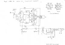
Quick 'n dirty...
OK, here's a quick and dirty sketch of the circuit using a 6SN7 instead of a 6SL7. Please forgive any mistakes, I did this in a hurry. The idea was to see if a 6SN7 would even work. I think it will, but not optimally. 6SN7 gets really linear with plate current of 8mA or higher. I couldn't pull more than 5mA per triode with this low a B+, so 5mA it is. Maybe someone else can figure a better way. I hope this is a decent start...
My apologies for the sloppy drawing.
--
I see that I forgot to bypass the cathode bias resistor for the first stage 6SN7. 220uF should work across that 330R.
Attachments
Last edited:
It seems that raising the plate voltage on the input stage causes it to clip earlier.
I doubt the first stage would clip earlier with More voltage swing possible. In fact, you'd have to be sending in quite a large signal to even get the first stage to clip. See my post just before yours and rongon's post just after. Your signal into the splitter is likely too high and overloading this, second, stage.
A higher B+ or more voltage swing for this stage would reduce this amps weak link.
Wouldn't it be better to have a CCS on top of the first 6SN7 and a Led under it ?
Yes. It would.
And I think it might also be better to use an LTP as the phase-splitter/driver, and put a negative supply and CCS in the tail.
Do you have two spare 100k Rs? If so, gator clip them each parallel to R14 and R9 and do your test again. This should increase both your Plate voltage swing limit as well as the available total swing.
I'll bet that would increase the possible swing through the cathodyne. But I have a question for you, out of curiosity. What would be the effect of a 50k plate and cathode load on that 6SL7? I mean, 50k ohms is appreciably less than the rp of a 6SL7. Gain would be reduced (so less negative feedback), gm would be less, rp would be higher (worsening the problem). I'm afraid it would be too nonlinear.
Then again, maybe I'm about to learn something?
")
Just out of curiosity, what is the voltage at pin 8 of the 6V6's?
The Bias on the 6v6's at pin 8 are 21 Volts for 5U4 and 22 Volts for the GZ34. I have those listed under 'Bias' in the measurments. The current Bias calculated to be a touch on the high side. The cathode resistor on is a 270 ohm and I recall it calculated out to be 37ma at 21Volts.
GoKite - I do have a couple, but just as easy to swap them out since it's all on the workbench. I was going to try a pair of 68K for R14 and R9 would that be a good test?
Sandy
The Bias on the 6v6's at pin 8 are 21 Volts for 5U4 and 22 Volts for the GZ34. I have those listed under 'Bias' in the measurments. The current Bias calculated to be a touch on the high side. The cathode resistor on is a 270 ohm and I recall it calculated out to be 37ma at 21Volts.
The grid bias on the 6V6 defines the limit of the voltage it can accept at its grid before overload. In other words, you need the driver stages to give you 21V peak (about 15Vrms) AC audio signal at the 6V6 output tube grids. That means your input tube needs to deliver that from the voltage it gets at its grid.
So if you use a 6SL7 with -0.5V grid bias, and supposing you get a good 50x gain from that 6SL7, that's 50*0.4 = 20V peak at the 6V6 grids. Not quite enough.
Remember that today's sources are supposed to deliver up to 2Vrms (2.83V peak) audio signal. A CD player is supposed to output 2Vrms at 0dBFS (full scale). You could design your amplifier to accept up to 2V at its input. Now remember that whatever negative feedback you apply will make the whole amp less sensitive -- adding negative feedback will make it so that it will take a higher voltage from the source to drive the amp to full power. 6dB negative feedback means a 2x drop in voltage sensitivity. In other words, if it took 2V to drive your amp to full power before negative feedback was added (open loop), it will take double that -- 4V -- to drive the amp after 6dB negative feedback has been added.
If you use a 6SN7 with -2.0V bias, and you figure your 6SN7 gets 14x gain, that's (being conservative here) 1.7*14 = 23.8V peak (about 17Vrms). That gets you there with just a little room to spare.
The resulting amp run without negative feedback would clip with 1.5V peak (about 1Vrms) at its input. If you apply 6dB NFB to the amp, its sensitivity will be halved, so it will now take 2Vrms to drive it to clipping. Conveniently, that is the full possible output from a CD player.
It looks to me that the simplest fix would be to abandon the 6SL7 and go with a 6SN7, and apply no more than 6dB NFB to the amp from the OPT secondary to the input tube cathode.
OK, I'll stop nagging now.
--
Last edited:
I'll bet that would increase the possible swing through the cathodyne. But I have a question for you, out of curiosity. What would be the effect of a 50k plate and cathode load on that 6SL7? I mean, 50k ohms is appreciably less than the rp of a 6SL7. Gain would be reduced (so less negative feedback), gm would be less, rp would be higher (worsening the problem). I'm afraid it would be too nonlinear.
Then again, maybe I'm about to learn something?
My suggestion was simply to provide a quick test for the OP to verify the issue as the PI. I believe i posted earlier i've never designed a cathodyne PI. In fact, i come from the guitar amp world and have an interest in building a home system, so i have been reading and watching diyaudio to pick up on the stuff you guys are doing, and why, so i can design my own hifi system.
Not looking at a set of curves, yes gain should be less, but the swing and headroom should increase, sending a higher-amplitude clean signal to the powertube(s) which would verify his/her issue in minutes. Again, just a quick test that could be done without even heating up the iron.
I'll give a few things a try, definitely will try out changing the PI's resistors just to see what happens. Easy and might have some different result.
I can try the 6SN7 route as well, I have plenty of parts for that, and it's not that complex of a change.
Hopefully I can catch a break in the next day or so to try a few things.
Can't thank everyone enough for all the tip, tech and suggestions.
Sandy
I can try the 6SN7 route as well, I have plenty of parts for that, and it's not that complex of a change.
Hopefully I can catch a break in the next day or so to try a few things.
Can't thank everyone enough for all the tip, tech and suggestions.
Sandy
Had a sliver of time. Some oddly interesting findings!
I ran the PI's resistors R9 and R14 to about 75k down from the 103k's that were installed. Clipping resulted at about the same 8.3VRMS. This is with the 5U4. The initial test with 103k seems slightly better. Didn't have time to capture all the data points.
Then got the iron out and pulled out R7 and changed it to a 1.2k
R9 and R14 to 33k
R8 to 47K
And put in a fresh nos GE 6SN7
Clipping again starts at about 8.7VRMS with the 6SN7!
From the other days test with the GZ34 and the 6SL7 ran right about the same. I'm watching the signal on the scope in the input and output and driving with a good signal source. Also looks like the 6SN7 requires about double the input for the same output. (Didn't mess at all with the FB loop).
The questions that I have could the 8K output transformer be a problem here, I had seen 6V6 output transformers run from 5K to the 8K range. The GE 6V6GT data sheet shows 8K Plate to Plate for PP AB1 amp with 285 Plate voltage. Might be a stretch, but figured I would toss it out since these are running HV1 (B+) right close to 350vdc. Hope that rating was what is to be used for the output transformer (Using Edcor GXPP15-8-8K)
That's my quick testing. Would have loved to see better or worse results but coming up similar, well leaves more room for exploring
Sandy
I ran the PI's resistors R9 and R14 to about 75k down from the 103k's that were installed. Clipping resulted at about the same 8.3VRMS. This is with the 5U4. The initial test with 103k seems slightly better. Didn't have time to capture all the data points.
Then got the iron out and pulled out R7 and changed it to a 1.2k
R9 and R14 to 33k
R8 to 47K
And put in a fresh nos GE 6SN7
Code:
Voltages -
HV1  : 343
HV2  : 335
HV3  : 317
Bias  : 22.9 (measured bias current with adapter and right at 37ma with 300ohm)
V1PA  : 134
V1PB  : 200
R8    : 182
R14   : 134
R9    : 135
R7 : 4.1From the other days test with the GZ34 and the 6SL7 ran right about the same. I'm watching the signal on the scope in the input and output and driving with a good signal source. Also looks like the 6SN7 requires about double the input for the same output. (Didn't mess at all with the FB loop).
The questions that I have could the 8K output transformer be a problem here, I had seen 6V6 output transformers run from 5K to the 8K range. The GE 6V6GT data sheet shows 8K Plate to Plate for PP AB1 amp with 285 Plate voltage. Might be a stretch, but figured I would toss it out since these are running HV1 (B+) right close to 350vdc. Hope that rating was what is to be used for the output transformer (Using Edcor GXPP15-8-8K)
That's my quick testing. Would have loved to see better or worse results but coming up similar, well leaves more room for exploring
Sandy
Last edited:
Also looks like the 6SN7 requires about double the input for the same output. (Didn't mess at all with the FB loop).
Yes, to be expected. Gain of 6SN7 is max of about 20X. Gain of 6SL7 is max of about 70X.
got the iron out and pulled out R7 and changed it to a 1.2k
R9 and R14 to 33k
R8 to 47K
And put in a fresh nos GE 6SN7
Code:
Voltages -
HV1 : 343
HV2 : 335
HV3 : 317
Bias : 22.9 (measured bias current with adapter and right at 37ma with 300ohm)
V1PA : 134
V1PB : 200
R8 : 182
R14 : 134
R9 : 135
R7 : 4.1
Clipping again starts at about 8.7VRMS with the 6SN7!
OK, with the 6SL7 in there, you get 8.3Vrms out from the amp. That equals 8.6 watts rms output.
With the 6SN7 in there, you get 8.7Vrms out from the amp. That equals 9.46 watts rms output. You increased the power out from the amp by 10%. I'd say that's progress.
Also, why did you change R8 to 47k? I think 39k would work just as well, and would allow you to bias the cathodyne in a better spot. (You can put 270k in parallel with the 47k resistor to get 40k.)
Also, You put 33k for the cathodyne plate and cathode resistors (R9 and R14), instead of 22k.
I don't understand your voltage chart. You say that for R8 you got 182V. Was that measured at the 6SN7 plate, or "above" the 47k resistor (in other words, you measured Ebb)?
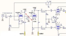
Since the 6SN7 input amp and cathodyne are DC coupled, the difference between the cathodyne cathode and grid MUST be -2V or thereabouts. It CANNOT be below -1V or so. (Remember that the first stage plate is directly connected to the second stage grid.) Therefore, a couple of vitally crucial measurements are:
- the voltage at the voltage amp's plate and
- the voltage at the cathodyne cathode.
You listed the B+ to the cathodyne as +335V. The voltages for a healthy cathodyne should be:
B+ = +335V
plate = +224V
cathode = +112V
That means the voltage at the voltage amp's plate MUST be about +110V.
The voltage at the cathodyne's cathode should be at least about +2V above the voltage amp's plate voltage.
Does your version measure in that ballpark?
--
The attached image shows what voltages go where. The next step would be to decide on how much current should go through each triode. I settled on about 5mA, because that allows me to put the same current through both the 1st and 2nd stages. That's how I arrived at R8 = 39k and R9, R14 = 22k. You can change that, but ONLY if the cathodyne stays biased correctly.
Attachments
Last edited:
I don't understand your voltage chart. You say that for R8 you got 182V. Was that measured at the 6SN7 plate, or "above" the 47k resistor (in other words, you measured Ebb)?
his HV is 317 so that has to be across the resistor (DMM leads on each side). his voltages confused me as well at first.
317 - 182 = 129 at input plate? 3.8mA
335 - 135 = 200V at PI plate? 4.1mA
Are these voltages DMMd with the 6SL7 or 6SN7?
6SN7 0-6.7mA with bias at 4mA is about -4V which R7 confirms. Gain is about (90-155)/4=16.25 (tungSol GT datasheet graph)
For the PI, graphically it is biased at 4mA which again puts the grid close to -4V which in this case is about 1V off center...looking at the DMM readings the input plate is DC coupled to the grid at 129V and the voltage on the cathode is 134V (R14) so it is -5V which checks out.
However, if he sends in a 2Vpp signal, the gain from input is 16 so that results in a 32Vpp input to the cathodyne which will run out of headroom quickly. The best thing is to increase the voltage to the cathodyne B+ which requires a new PT. trying to squeeze the most out of it by lowering the gain of the input stage? Seems to me the cathodyne can handle about 12Vpp before unwanted distortion? Or a voltage divider between stages? or feedback between the plate and grid of the input stage? or, or, or...is there a cap for C6 in the build?
Lots to reply to!
The Voltages listed are with the GZ34 and 6SN7. The result of 8.7VRMS is lower then the original GZ34 and 6SL7 which clipped right around 9VRMS. So lost some ground vs. the best results with the GZ34 in the original configuration.
Voltages for R7,R8,R9, R14 are measured across the resistor not to ground.
Rongon - On the values for the resistors (47k/33k), I pulled the ones from a different post by mistake, was a late night. I'm going to try the values you suggested and see what it does and gather new voltages.
Gokite - C6 is not installed. Left open as an optional component.
Part of the problem with the amp could be the name, it's called the EZ10, but I should have started with the NOTSOEZ-8.6
Going to try to hit the correct components tonight if I'm able to operate a dangerous soldering iron late at night!
Sandy
- Status
- This old topic is closed. If you want to reopen this topic, contact a moderator using the "Report Post" button.
- Home
- Amplifiers
- Tubes / Valves
- New 6V6 Build - Suggestions Needed