Not quite sure what typical pre-amps deliver, or CD players for that matter, but found this -
Line level - Wikipedia, the free encyclopedia
I have a Dynaco Pas-3 and will see if the manual has the specs for output.
Line level - Wikipedia, the free encyclopedia
I have a Dynaco Pas-3 and will see if the manual has the specs for output.
Some recommended reading that is pretty easy to understand see Steve's Tube Pages follow the links loadlines 1 - 5
Last edited:
I am not surprised in the least that you lost available voltage swing by just raising the plate voltage since this circuit depends on the correct operating points. In my previous post a couple pages back I gave the optimum operating point for your available B+. The 110 volts on the plate was quoted because it is 1/3 the B+ of the PI which is where the grid and cathode needs to be. raising above or below this will over/under bias the tube. Using the 220k on the input plate and 100k on plate/cathode of the PI and 110 volts is optimum for this circuit. I tested with a quick sim using 12ax7 at these same operating points and got 40 volts rms from the PI outputs. I didnt speculate when giving you this info I did the math and checked before posting as I do not like to steer anyone the wrong way. Your clipping issues are A) the original schematic, the input tube runs out of bias voltage quickly and clips due to onset of grid current and B) the change to 150k plate load, raising the plate voltage so that now the PI tube runs out of bias voltage and clips due to onset of grid current. Using dc coupling with this circuit requires a balancing act, simply changing things and seeing what happens just won't get you anywhere. If you make the changes I stated in my previous post and you still can't get at least 12 watts out then there is something else wrong going on.
Some recommended reading that is pretty easy to understand see Steve's Tube Pages follow the links loadlines 1 - 5
I agree with all of the above.
Yes, with approximately +335V available B+ for the PI (what I call the phase splitter, or "cathodyne"), you'll want to have the plate resistor drop about 1/3 of the total B+ to ground, the cathode resistor drop 1/3, and then the tube will drop 1/3. One-third of +335V is about +112V (or +110V is certainly close enough).
Now, since the input stage is DC coupled to the phase splitter stage, the plate voltage of the first (input) stage will need to be 2V lower (more negative) than the cathode of the second stage. So if the second stage cathode voltage is +112V, then the plate voltage of the first stage MUST be +110V (or very close to that). That's just exactly as jerluwoo posted.
That right there is the most important couple of voltages in this particular amplifier, and maybe the trickiest to get just right. You really can't just change one thing here and another thing there, and expect to get anywhere. The two stages are intertwined. Change something in the first stage and it changes the DC conditions of the second stage.
jerluwoo said:In my previous post a couple pages back I gave the optimum operating point for your available B+. The 110 volts on the plate was quoted because it is 1/3 the B+ of the PI which is where the grid and cathode needs to be. raising above or below this will over/under bias the tube. Using the 220k on the input plate and 100k on plate/cathode of the PI and 110 volts is optimum for this circuit.
You could just do that with the 6SL7 and it will work. 40Vrms output from the phase splitter is pretty impressive. You'd be able to drive your 6V6's with lots of room to spare.
Or you could switch to a 6SN7 and use the parts values I gave you. That should give you about 30Vrms of output from the phase splitter. Also enough to drive the 6V6's with room to spare.
(6SN7 mu = 20. I'll figure on a real world, attainable amplification factor of 15X. 2*15 = 30Vrms. 30Vrms = 42V peak)
The point is that it's more important to design the circuit correctly than it is to choose any particular tube. The choice of tube is personal taste, etc. but it is mandatory to get the DC conditions right.
gokite said:What is a typical hifi input voltage p-p? I read somewhere on this forum 2V pp or 2Vrms was typical of a CD player. Is this true?
Yes, a CD player is supposed to output 2Vrms AC audio signal at 0dBFS (full blast).
2Vrms = 2.83V peak
Most analog sources like RIAA preamps and FM tuners put out a bit less than this, so most amplifiers are designed to be driven to full output (just short of clipping) with about 1Vrms of input.
--
Last edited:
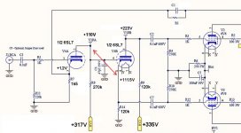
To follow up on the previous post, jerluwoo wrote that the first stage plate voltage should be +110V. In post #57 of this thread, I took a part of your schematic and drew some new voltages, including +110V on the first stage plate, and put a red arrow between the first stage plate and second stage cathode, to show the relationship there.
The grid bias of the second stage is defined by the difference between the voltage on its grid (which is directly connected to the first stage plate) and the voltage on its cathode.
If the first stage plate is at +110V (and therefore the second stage grid), and the second stage cathode is at +112V, then the "grid bias" on the second stage is -2V.
In your original circuit, it looked like the grid bias on the second stage was less than -0.5V. That's too close to zero for a 6SL7.
Do you see the problem?
--
I made a quick stab at plugging values in for a 6SL7 driver stage. I got 120k for the plate and cathode load resistors for the cathodyne. Not a big difference from the 100k jerluwoo suggested. From what I can tell, either would work. That one's a judgement call.
Attachments
Last edited:
OK, I drew some loadlines for the cathodyne using a 6SL7. I hope this will be informative. The illustration is attached.
It looks to me like the single most important thing you can do is change R8 (first stage plate resistor) to 270k ohms, and change R7 to 1500 ohms. That will put the plate of the first stage 6SL7 at +110V, or very close to it. That's the single most important thing to do to get the DC conditions correct.
If I'm reading the loadlines correctly, the original 150k for R9 and R14 should work. The 6SL7 will be drawing about 0.742mA, and the grid bias (Vg-k) will be -1.2V. To check this, 150,000 ohms*000742A = 111.3V, which is close enough.
For R9 and R14, 120k and 100k work out too. I'm not sure which of the three choices would work out best in real life, because the slop factor from variations in tube characteristics makes it useless to quibble over a tenth of a volt here or there. Try whatever you have and see.
But the single most important thing is to get that first stage set up exactly like jerluwoo said. R8 = 270k, R7 = 1500R. Or R8 = 220k and R7 = 1k.
--
Oops, I see jerluwoo recommended 220k for R8. I guess we have a slightly different way of reading loadlines. Any reason why you went with that value?
Attachments
Last edited:
It seems that things are much more critical then I ever expected, my perceived allowable slop in tollerence with the design has been totally wrong!
So to keep things from getting more confusing on the testing this is what I'm going to try. I'll lay it out just to make sure it's the right direction.
Going back to the 6SL7 as tube of choice, and the GZ34 for rectifier. R16 at 4.7K (Was originally 47k).
Then For The Following tests -
Test 1
R8 = 270k, R7 = 1.5k, R9 & R14 150k
Test 2
R8 = 220k R7 = 1k, R9 & R14 150k
I should have all of those values in the bin, so just a matter of catching a break to do the testing.
You guys have been more then awesome (and patience) walking me through this. I was going to do a quad KT88 amp, but glad I built this one first!
Sandy
Well thanks guys, I learned how to DC couple a cathodyne this AM.
How did I write -4v bias and not pick up the limited swing?
the written voltages on the original schematic on OP post page 1 are looking weird:
Using plate current through 270k. B+=220, Rp=270k and plate voltage=90, the LL shows 0-0.8mA biased at 0.48mA (220-90 = 130v drop across 270k) 130/270000 = 0.48mA = -1.5V bias on graph
Using this 0.48mA through 1k Rk we get -0.5V bias
These don't match up, not even close. Unfortunately there is no voltage marked on the cathode of the first gain stage.
I assume the DC coupled cathodyne draws current through it's grid and the 270k but will it really be this much? or are the voltages probably a little off?
Having learned what I learned this AM, I would assume at this point to just go back to the original schemo, and for changes just raise the Rk on stage one to 1k5 like suggested and maybe reduce R16 from 47k to 33k or 27k. if you do this you can probably bias the first stage with a 1k8 instead of 1k5 for a bit more headroom. You should be able to also use a simple voltage divider btwn the plate and grid to get higher DC voltage on the input plate to give the input more headroom. Adding two resistors on the cathodyne grid with one going to ground and the other to the plate of the input should do this and still maintain the proper ~110VDC grid potential (yes?).
Also one more thing rongon, I believe your graphs are reversed. The 270k Rp goes with a 220B+ and the PI load line goes with the 335 B+. I also think the load line with 100k resistors should show 200k slope (Rp+Rk), not a single resistor. The attached shows 335B+ with a total swing of 335-50=~280Vpp/2=140Vpp=50Vrms
Plate at ~220, 0.51mA. 335-220=115/0.00051=225k/2=110k resistors for Rp/Rk
Am I doing this right? 50Vrms is overkill for 6V6. Can use EL34, which is what I was planning to use. (how does one attach a thumbnail?)
Gokite:
6SN7 0-6.7mA with bias at 4mA is about -4V which R7 confirms. Gain is about (90-155)/4=16.25 (tungSol GT datasheet graph)
How did I write -4v bias and not pick up the limited swing?
jerluwoo:
the original schematic, the input tube runs out of bias voltage quickly and clips due to onset of grid current
the written voltages on the original schematic on OP post page 1 are looking weird:
Using plate current through 270k. B+=220, Rp=270k and plate voltage=90, the LL shows 0-0.8mA biased at 0.48mA (220-90 = 130v drop across 270k) 130/270000 = 0.48mA = -1.5V bias on graph
Using this 0.48mA through 1k Rk we get -0.5V bias
These don't match up, not even close. Unfortunately there is no voltage marked on the cathode of the first gain stage.
I assume the DC coupled cathodyne draws current through it's grid and the 270k but will it really be this much? or are the voltages probably a little off?
Having learned what I learned this AM, I would assume at this point to just go back to the original schemo, and for changes just raise the Rk on stage one to 1k5 like suggested and maybe reduce R16 from 47k to 33k or 27k. if you do this you can probably bias the first stage with a 1k8 instead of 1k5 for a bit more headroom. You should be able to also use a simple voltage divider btwn the plate and grid to get higher DC voltage on the input plate to give the input more headroom. Adding two resistors on the cathodyne grid with one going to ground and the other to the plate of the input should do this and still maintain the proper ~110VDC grid potential (yes?).
Also one more thing rongon, I believe your graphs are reversed. The 270k Rp goes with a 220B+ and the PI load line goes with the 335 B+. I also think the load line with 100k resistors should show 200k slope (Rp+Rk), not a single resistor. The attached shows 335B+ with a total swing of 335-50=~280Vpp/2=140Vpp=50Vrms
Plate at ~220, 0.51mA. 335-220=115/0.00051=225k/2=110k resistors for Rp/Rk
Am I doing this right? 50Vrms is overkill for 6V6. Can use EL34, which is what I was planning to use. (how does one attach a thumbnail?)
An externally hosted image should be here but it was not working when we last tested it.
Last edited:
Quick note, the voltages on the schematic were some baseline numbers that I had found from the original Slivertone amp. I should have made it clear that they were never anything that was tested, but more notes to see were the values come up on power up. Should have left more notes on the schematic as to that.
gokite - To attach the thumbnail scroll down below the "Reply to Thread" box and you will see a button that says MANAGE ATTACHMENTS mash that button and you will see a way to upload images.
I think the only thing that I'm a bit fuzzy on is the value for R16. I have a 4.7k in for it and will set up the first test with the 6SL7 with it to see what the voltages look like.
Sandy
Hey gokite, great post, and I'm glad to hear that you got into figuring the DC coupling in this circuit. Fun, ain't it?
The loadline with the 100k resistor is for the cathodyne (second stage). From what I've read, you figure the horizontal-axis voltage from B+ to cathode (so +335V - +110V = +225V), and then 225/100k = .00225A (or 2.25mA) on the vertical-axis. I could be totally wrong. If so, please correct me!
I've been scratching my head over the voltage measurements since the beginning of this thread. I hope we can get a definitive, verified set of V measurements at some point.
The last set of voltages reported listed the B+ to the first stage as +317V, and that's what (I thought) I used to arrive at my suggestions for 270k plate resistor and 1.5k cathode resistor. Previous suggestions may have been made to accommodate a lower B+ to the first stage. I can easily see how things would be totally confused at this point.
The cathodyne should not draw grid current. You want the cathodyne to have a nice, high input impedance, to make it an easy load for the first stage. If it draws grid current, its input impedance will plummet, and that will distort the output from the first stage. That is what I believe the problem has been all along, but I'm not 100% sure of this because we've never been given a set of definitive voltages for all the various points in the circuit.
--
PS -- I did goof up the loadline for the first stage. The B+ (horizontal axis) should be +317V, not +335V. D'OH! Good catch!!
the load line with 100k resistors should show 200k slope (Rp+Rk), not a single resistor.
The loadline with the 100k resistor is for the cathodyne (second stage). From what I've read, you figure the horizontal-axis voltage from B+ to cathode (so +335V - +110V = +225V), and then 225/100k = .00225A (or 2.25mA) on the vertical-axis. I could be totally wrong. If so, please correct me!
I've been scratching my head over the voltage measurements since the beginning of this thread. I hope we can get a definitive, verified set of V measurements at some point.
The last set of voltages reported listed the B+ to the first stage as +317V, and that's what (I thought) I used to arrive at my suggestions for 270k plate resistor and 1.5k cathode resistor. Previous suggestions may have been made to accommodate a lower B+ to the first stage. I can easily see how things would be totally confused at this point.
I assume the DC coupled cathodyne draws current through it's grid and the 270k but will it really be this much? or are the voltages probably a little off?
The cathodyne should not draw grid current. You want the cathodyne to have a nice, high input impedance, to make it an easy load for the first stage. If it draws grid current, its input impedance will plummet, and that will distort the output from the first stage. That is what I believe the problem has been all along, but I'm not 100% sure of this because we've never been given a set of definitive voltages for all the various points in the circuit.
--
PS -- I did goof up the loadline for the first stage. The B+ (horizontal axis) should be +317V, not +335V. D'OH! Good catch!!
Last edited:
OK, corrections to my post from late last night (with thanks to gokite for checking my work!) 
For the first stage, using a B+ of +315V:
If you use 270k for R8, use 1.3k for R7.
If you use 220k for R8, use 1.8k for R7.
You could probably use 1.5k for R7 in either of the above, but just make sure that if Vp for the first stage 6SL7 = +110V that the Vk for second stage 6SL7 = +111.5 or thereabouts. In other words, make sure the voltage between the second stage 6SL7 grid and second stage 6SL7 cathode is -1.5V or thereabouts. Also make sure the Vk for the first stage is +1.2V or thereabouts.
Phew!
--
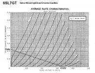
My graph is for the cathodyne as well. B+ 335 from OP post #1. the tube sees current through the whole tube so using 100k s on the Ra and Rk represents a total load of 200k. So 335/200,000 is the LL. Center bias is shown as the red dot. This is roughly 2/3 the B+ as per the "rule of thumb" 1/3, kinda interesting how that works out. With a 4k7 instead of 47k for the rail, the plate voltage will be higher o n the input stage and the bias of the catodyne will prob be off. Also i do believe that no matter what, the grid will draw "some" current but it should be minor, perhaps 5% of the total current through the tube and can probably be ignored for calculation. After all this is a cathode follower, and a CF draws some grid current. Please someone correct this so I have it straight if they know for sure this is wrong.
My graph is for the cathodyne as well. B+ 335 from OP post #1. the tube sees current through the whole tube so using 100k s on the Ra and Rk represents a total load of 200k. So 335/200,000 is the LL. Center bias is shown as the red dot. This is roughly 2/3 the B+ as per the "rule of thumb" 1/3, kinda interesting how that works out. With a 4k7 instead of 47k for the rail, the plate voltage will be higher o n the input stage and the bias of the catodyne will prob be off. Also i do believe that no matter what, the grid will draw "some" current but it should be minor, perhaps 5% of the total current through the tube and can probably be ignored for calculation. After all this is a cathode follower, and a CF draws some grid current. Please someone correct this so I have it straight if they know for sure this is wrong.
The following is to the best of my knowledge, hopefully in accordance with Morgan Jones' excellent description of how a "concertina" (what I call a "cathodyne") phase splitter works. That's in his book "Valve Amplifiers." Read starting from page 403 in the 3rd edition, and also look at the DC conditions part of the description of the Bevois Valley amplifier design (page 446) -- which should look very familiar...
Yes, the current goes through the whole tube, but the cathodyne is a special case because it's a phase splitter. The cathodyne goes back and forth between outputting a positive going signal and a negative going signal. So it alternates between the current being drawn across its plate load (negative swing) and its cathode load (positive swing). The current through the tube remains constant. The current between the loads swings back and forth.
That is why the B+ has to be looked at from B+ to cathode in one direction, and plate to ground in the other direction. Not from the total B+ to ground, because then you have two loads, each drawing the same current (Ip or Ik, which are identical).
With a B+ of +335V (measured from the B+ feed to ground), the B+ to cathode voltage is +225V, while the plate to ground voltage is also +225V. One draws the cathodyne load lines from those points.
Another way to look at it is to divide the available B+ into thirds. 1/3 the B+ is dropped across the plate load resistor, Rp. 1/3 the B+ is dropped across the cathode load resistor, Rk. The last 1/3 of the B+ is dropped across the tube. The current is the same at all points in the circuit.
Now make the voltages make sense. Since the Vp (plate voltage) of a tube is plate-to-cathode, it will be only 1/3 of the B+, not 1/2 to 2/3 of the B+ like it would be with a common cathode amplifier (with a very small cathode-to-ground voltage).
I think that helps explain it. I think...
--
Last edited:
Ok thanks for that explanation. I don't have that book. My method seemed to work and after I posted I started looking around and found this which says my method is correct:
The Valve Wizard
" For example, the load line below shows a total load of 200k, or in other words, the anode and cathode resistors are 100k each."
Funny that this example is exactly the same with two 100k's, so which is correct? In my original thinging, the resistors are simply split, but in the path, so regardless of which direction the current flows, there is 200k resistance. If I ever get the book you cite, I'll check it, unless someone can scan and upload a pdf of that page, though that is prob a violation of some copyrighting/publishing rule I'm sure.
I just ordered the book, will have it in a couple of days. I has also seen the valvewizard site and saw they use both resistors to calc the load line but that's just my limited knowlege of what they were saying
I will get the testing going as soon as I can and will get a lot of measurements with the recommended parts.
Sandy
I will get the testing going as soon as I can and will get a lot of measurements with the recommended parts.
Sandy
I chose the 220k for the plate so that the voltage/current of the tube would give a bias of at least 1 volt according to the rca datasheet I was using for the plate curves. Looking at the GE datasheet shows this point as giving 1.5 volts bias which is good too so long as there is at least 1 volt available for input swing.
One question I havn't seen yet, since we've been discussing the front end, is the plate to plate impedance of the output transformer. I have not seen its spec given or perhaps overlooked it. Having the wrong impedance can and will cause it not to reach the correct power output as well
One question I havn't seen yet, since we've been discussing the front end, is the plate to plate impedance of the output transformer. I have not seen its spec given or perhaps overlooked it. Having the wrong impedance can and will cause it not to reach the correct power output as well
Last edited:
Thanks gokite for pointing me to the Valve Wizard site (which I should have remembered from the last person who pointed me there!). What's really nice about that explanation is that it's so simple. Even an idiot like me can get it, and quickly.
Well, I may have misunderstood the method for calculating a loadline for a cathodyne ("split load" or "concertina") phase splitter. I don't know. But I gave the Valve Wizard method a try, to see what I'd get.
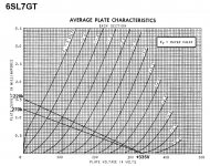
So, with a B+ of +335V and Rp and Rk of 150k, I got the loadline in the attached graphic.
According to the Valve Wizard method,
335V/300,000 ohms = .00116A (1.1mA will be close enough)
So I drew the loadline from +335V to 1.1mA, as in the attached graphic.
Remembering that a 6SL7 will draw grid current at about -0.5V grid bias, and that I wanted to stay out of the "knee" (cutoff) region of the curves, where they bunch up at low current, I picked my center point at Vp = +125V.
So, that puts the operating point at Vp = +125, Eg = -1.5V, and Ip = 0.7mA
0.0007A * 150,000 ohms = 105V dropped across each 150k resistor.
105V*2 = 210V, leaving 125V across the tube (plate to cathode).
So now we need to put the plate voltage (Vp) of the first tube at +123.5V, precisely.
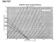
With +315V of B+ for the first stage, that means we need to drop 191.5V across the Rp of the first stage 6SL7. Believe it or not, a plate load (Rp) of 270k will do that! That's in the second graphic, which is the first stage loadline with B+ = +335V, Rp = 270k.
Choosing the required Vp of +123.5V, the Ip = 0.7mA (Wow! The same as for the second stage!) and the grid bias needs to be just about -1.5V. (Perfect!)
So, to solve for the value of Rk (cathode resistor),
1.5V/0.0007A = 2,142 ohms.
2k2 should be close enough.
So there you have it. According to the Valve Wizard method, all the values come out exactly the same as before, except for the cathode bias resistor of the first stage, which comes out to 2k2 instead of 1k5.
I suppose Sandy will tell us which value of Rk proves correct in the end.
Thanks gokite. I think I learned something.
--
Well, I may have misunderstood the method for calculating a loadline for a cathodyne ("split load" or "concertina") phase splitter. I don't know. But I gave the Valve Wizard method a try, to see what I'd get.
So, with a B+ of +335V and Rp and Rk of 150k, I got the loadline in the attached graphic.
According to the Valve Wizard method,
335V/300,000 ohms = .00116A (1.1mA will be close enough)
So I drew the loadline from +335V to 1.1mA, as in the attached graphic.
Remembering that a 6SL7 will draw grid current at about -0.5V grid bias, and that I wanted to stay out of the "knee" (cutoff) region of the curves, where they bunch up at low current, I picked my center point at Vp = +125V.
So, that puts the operating point at Vp = +125, Eg = -1.5V, and Ip = 0.7mA
0.0007A * 150,000 ohms = 105V dropped across each 150k resistor.
105V*2 = 210V, leaving 125V across the tube (plate to cathode).
So now we need to put the plate voltage (Vp) of the first tube at +123.5V, precisely.
With +315V of B+ for the first stage, that means we need to drop 191.5V across the Rp of the first stage 6SL7. Believe it or not, a plate load (Rp) of 270k will do that! That's in the second graphic, which is the first stage loadline with B+ = +335V, Rp = 270k.
Choosing the required Vp of +123.5V, the Ip = 0.7mA (Wow! The same as for the second stage!) and the grid bias needs to be just about -1.5V. (Perfect!)
So, to solve for the value of Rk (cathode resistor),
1.5V/0.0007A = 2,142 ohms.
2k2 should be close enough.
So there you have it. According to the Valve Wizard method, all the values come out exactly the same as before, except for the cathode bias resistor of the first stage, which comes out to 2k2 instead of 1k5.
I suppose Sandy will tell us which value of Rk proves correct in the end.
Thanks gokite. I think I learned something.
--
Attachments

One question I havn't seen yet, since we've been discussing the front end, is the plate to plate impedance of the output transformer. I have not seen its spec given or perhaps overlooked it. Having the wrong impedance can and will cause it not to reach the correct power output as well
I mentioned it but it would be easy to get lost in all the conversation! It's an 8k 15watt Edcor unit. The part number is in one of the previous post, (Using Edcor GXPP15-8-8K)
And will update the Cathode resistor to 2.2k (will also try others). I think early in the thread I had posted the chart of the recommended parts and was thinking that the 1k was too low only because of the values on the chart seemed to indicate it for the ebb that was being used. Was something like 2.1k for RK and 240k for RP. (chart from GE was on post #14)
Last edited:
Ok, have my work project about done and under control so I can get back and work on the 'Real' project
Here is the first test. This is with the GZ34, R16=4.7K, All tubes in and no signal applied.
R7=1.2K
R8=220K
R9=R14=150k
Voltages
HV1=346
HV2=345
HV3=339
BIAS=23.1
R7=1.1
R8=224
R9=113.7
R14=114.9
Clipping at 9.03VRMS into 8ohm load. This was about the same as the original circuit values with the GZ34.
I think the suggestion for R7 with a R8=220K was more like 1.8k but I had so will make that the next test to see what happens when R7 moves from 1.2k to 1.8K (or closest I have).
Once I get the change in R7 done and measured, will try R8 as 270K and R7 as 2.2K which I think was the final best values that were obtained
Sandy
Thanks gokite for pointing me to the Valve Wizard site (which I should have remembered from the last person who pointed me there!). What's really nice about that explanation is that it's so simple. Even an idiot like me can get it, and quickly.
Well, I may have misunderstood the method for calculating a loadline for a cathodyne ("split load" or "concertina") phase splitter. I don't know. But I gave the Valve Wizard method a try, to see what I'd get.
So, with a B+ of +335V and Rp and Rk of 150k, I got the loadline in the attached graphic.
According to the Valve Wizard method,
335V/300,000 ohms = .00116A (1.1mA will be close enough)
So I drew the loadline from +335V to 1.1mA, as in the attached graphic.
Remembering that a 6SL7 will draw grid current at about -0.5V grid bias, and that I wanted to stay out of the "knee" (cutoff) region of the curves, where they bunch up at low current, I picked my center point at Vp = +125V.
So, that puts the operating point at Vp = +125, Eg = -1.5V, and Ip = 0.7mA
0.0007A * 150,000 ohms = 105V dropped across each 150k resistor.
105V*2 = 210V, leaving 125V across the tube (plate to cathode).
So now we need to put the plate voltage (Vp) of the first tube at +123.5V, precisely.
With +315V of B+ for the first stage, that means we need to drop 191.5V across the Rp of the first stage 6SL7. Believe it or not, a plate load (Rp) of 270k will do that! That's in the second graphic, which is the first stage loadline with B+ = +335V, Rp = 270k.
Choosing the required Vp of +123.5V, the Ip = 0.7mA (Wow! The same as for the second stage!) and the grid bias needs to be just about -1.5V. (Perfect!)
So, to solve for the value of Rk (cathode resistor),
1.5V/0.0007A = 2,142 ohms.
2k2 should be close enough.
So there you have it. According to the Valve Wizard method, all the values come out exactly the same as before, except for the cathode bias resistor of the first stage, which comes out to 2k2 instead of 1k5.
I suppose Sandy will tell us which value of Rk proves correct in the end.
Thanks gokite. I think I learned something.
--
Please note that the cathodyne, as the cathode follower, operates under 100% almost feedback. This means that the grid voltage does not stray off the bias point you choose. Now enjoy more freedom in designing that stage!
Here is the second test. This is with the GZ34, R16=4.7K, All tubes in and no signal applied.
R7=2.2K
R8=270K
R9=R14=150k
Voltages
HV1=348
HV2=347
HV3=343
BIAS=23.3
R7=1.45
R8=215
R9=125
R14=126
Clipping at 9.1VRMS into 8ohm load. Possibly a tick better then the previous test. A bit over 10 watts.
The numbers you calculated for the VP and VK of the input look to be about what you have in your last calculation. Numbers seem to work, might be the best that can be had with the design. I'm going to drill out a test chassis to mount all the mess up the plug into a speaker to see what it sounds like.
Sandy
- Status
- This old topic is closed. If you want to reopen this topic, contact a moderator using the "Report Post" button.
- Home
- Amplifiers
- Tubes / Valves
- New 6V6 Build - Suggestions Needed