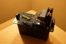
Take some really detailed pix of the interior of your chassis to show us how the grounding, filament wiring, HV supply are done, where the power and output transformers are located & oriented relative to each other - choke too if you are using one.
RCA jack is isolated from chassis and connected at the amp star ground?
RCA jack is isolated from chassis and connected at the amp star ground?
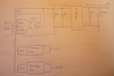
I think there are two serious error in the power supply (based on the pictures).
1.) HV CT point connected to the e-choke ground (?) /black wire/, then e-choke other side ground(?) connected to the star ground.
2.) Where is the first 10uF capacitor? (IMHO 10uF too low for e-choke applications)
If the e-choke connected inversely, works like the short circuit (AC mode).
1.) HV CT point connected to the e-choke ground (?) /black wire/, then e-choke other side ground(?) connected to the star ground.
2.) Where is the first 10uF capacitor? (IMHO 10uF too low for e-choke applications)
If the e-choke connected inversely, works like the short circuit (AC mode).
Last edited:
Any good result of your baby? Actually I am starting to build the clone 09s as well, so that any information of you guys is very important to me. I am going to use Tomchr high voltage supply for my baby. Thanks.
An externally hosted image should be here but it was not working when we last tested it.
Hi Euro21
I have tried some changes but with little result:
1) changed ground path, HV CP to star ground and E-choke ground to star ground:
Measurements:
before adding 330uF
output from e-choke = 448V 1,5Vac
output from MEC50 = 454V 2,2Vac
after adding 330uF
output from e-choke = 443V 356mVac
input to MEC50 = 443V 356mVac
output from MEC50 = 437V 180mVac
So still to much noise
What to do next
Do you think changing the G2 voltage divider will change something ?
3.) G2 voltage divider.
(454V-186V)/221K= 1.21mA
Original 09S divider (55K+33K) operate at 4.5mA!
I have tried some changes but with little result:
1) changed ground path, HV CP to star ground and E-choke ground to star ground:
Same result, no difference
2) Added a 330uF capacitor after the e-choke and moved MEC50 to after e-choke:Reduced output noise from 58mV to 15mV but still way too much
Measurements:
before adding 330uF
output from e-choke = 448V 1,5Vac
output from MEC50 = 454V 2,2Vac
after adding 330uF
output from e-choke = 443V 356mVac
input to MEC50 = 443V 356mVac
output from MEC50 = 437V 180mVac
So still to much noise
What to do next
Do you think changing the G2 voltage divider will change something ?
3.) G2 voltage divider.
(454V-186V)/221K= 1.21mA
Original 09S divider (55K+33K) operate at 4.5mA!
Last edited:
A: "Where is the first 10uF capacitor?"
Adding capacitance AFTER the e-choke not harmfull, but not sufficent, if C1 (10uF) missed, or low.
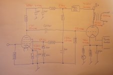
Schematic:
GZ37 rectifier diode -> C1 -> e-choke -> C2 - > R(100R) -> C3 -> OPT -> 300B
-> MEC50 -> R(33K) -> C4+C5
-> R(221K) -> C6
->R(100K)
In the picture I see only three large PP capacitors: C4+C5, and C6.
C1, C2, C3 are connected (CORRECTLY !) to the back panel under the e-choke?
B: "Do you think changing the G2 voltage divider will change something ?"
After solving the hum problem can be interesting.
Adding capacitance AFTER the e-choke not harmfull, but not sufficent, if C1 (10uF) missed, or low.
Schematic:
GZ37 rectifier diode -> C1 -> e-choke -> C2 - > R(100R) -> C3 -> OPT -> 300B
-> MEC50 -> R(33K) -> C4+C5
-> R(221K) -> C6
->R(100K)
In the picture I see only three large PP capacitors: C4+C5, and C6.
C1, C2, C3 are connected (CORRECTLY !) to the back panel under the e-choke?
B: "Do you think changing the G2 voltage divider will change something ?"
After solving the hum problem can be interesting.
The C1 Capacitor is under the E-Choke.
I have tried replacing the e-choke with a 5H choke I had from a other project, this changed B+ alot....
440V 100mVac
Output noise is reduced to 3,7mV still too much, but much better...
I don't think the E-choke is doing it's job
I have tried replacing the e-choke with a 5H choke I had from a other project, this changed B+ alot....
440V 100mVac
Output noise is reduced to 3,7mV still too much, but much better...
I don't think the E-choke is doing it's job
Attachments
Ok, good news.
The E-choke bug fixed a lot
B+ now has 10mV ac noise
And output noise is down to 2mV ac, hope I can improve this a little more when I get the layout cleaned up after all the trouble shooting.
But the MEC50 still isn't working as expected, will try to increase the current through it, to see if that changes things ?
Thanks for all the help
Suggestions for further improvements are welcome
Attachments
yamamoto A-09s design
Hi everyone,
I'd like to add a few comments. I am using C3M-300B topology for a few years now, I was experimenting with number of drivers for 300b, including number of C3M topologies.
From a number of available C3M-300B schematics, Yamamoto A-09S is probably the worst design. Yamamoto-sun basically copied Weco91 design, just replacing we810 driver with C3M and finding suitable G2 voltage ....well, Western Electric engineers use whatever tube was available that time. As a result driver runs with 91K anode resistor and rolling down at about 16 KHz due to Miller C of 300b. C3M is capable of running at 16ma anode I with 10K anode R, bringing bandwidth to 400kHz. That is Siemens recommended operation,,
150V G2, 10K anode R and 250 R cathode R. That i more or less the topology in Thorsten "Legacy" and Italian amp in Glass Audio. With some little tweaking, that is probably the best driver available.
Another note is regarding mentioned "electronic choke" . Please note that "real" choke is storing energy, where "electronic" is just a filter. It makes a huge deference in PS for power amplifier. Also, regulated DC heater supply for indirect heated C3M is waist of resources IMHO.
Someone may disagree with me, it is OK. Just built c3m/300b with really good output transformers , best c3m-300b coupling caps and (highly recommended) with non-electrolytic, oil caps in power supply. Then try both C3M topologies , measure amplitude/frequency and distortions and, most important, listen what sounds best to you.
BTW, what is IMHO is really great about A-09 is film caps in PS and 300B cathode. However 20uF for 300b cathode is a bit too low, bringing 20Hz to -2dB and, more important, changing LF phase. 33uF is a minimum, better 47. Oh, and speaking of a-09s PS. Yamamota-sun uses 400v film caps in the c3m B+ . It is OK when c#m is in-place. Without C3M 400v cap sees 435v across. Not exactly great engineering.
Thanks,
Alex
Ok, good news.
The E-choke bug fixed a lot
B+ now has 10mV ac noise
And output noise is down to 2mV ac, hope I can improve this a little more when I get the layout cleaned up after all the trouble shooting.
But the MEC50 still isn't working as expected, will try to increase the current through it, to see if that changes things ?
Thanks for all the help
Suggestions for further improvements are welcome
Hi,
Your G2 chain is not working properly: you have 220k + 100k connecting B+ to G2/ Zeners. Current is 435-65 / 320 = 1.1 ma
C3M runs at 435-115/133=2.4 ma
G2 current is about 1/4 of Ia = 0.6 ma
That makes current flow through Zeners 1.1 - 0.6 = 0.5 ma Way not enough ! BTW in A-09s Zeners supplies via 50k+33k resistors.
Schematics of the Yamamoto A-09s is published somewhere in this thread, I strongly recommend you not to try make it better before you know exactly how it works,
just follow the design.
Good luck,
Alex
- Status
- This old topic is closed. If you want to reopen this topic, contact a moderator using the "Report Post" button.
- Home
- Amplifiers
- Tubes / Valves
- Yamamoto 09S 300B SE Amp Problem