Really dun understand why the voltage draw to. I'm not sure is driver tube socket related or not.
Last night last experiments was disconnected all & re-do everything. I did on 1 driver stage alone without power stage. measurement look good. after hook up to power stage. the voltage dropped.
Now give me another question mark whether power stage is the root cause.
Last night last experiments was disconnected all & re-do everything. I did on 1 driver stage alone without power stage. measurement look good. after hook up to power stage. the voltage dropped.
Now give me another question mark whether power stage is the root cause.
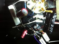
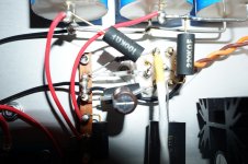
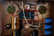
Following are snapshot of my tube amp driver stage. initially i'm using star grounding, then after than I switch to ground bus.
anyway, make no different.
Please keep pictures smaller, many have net books or I-Pads slower Wi-Fi, whatever. I fixed those already, just keep it in mind. Thanks.

Thanks for everyone advises.
For time being, I modified my driver stage from c3m to 6SN7 while waiting for tube socket.
After modification, my 300b immediately working without any issue as mentioned above except power on time have "pop" sound. & this problem also solved by installed timer delay to delay on GROUND.
Cheers....
For time being, I modified my driver stage from c3m to 6SN7 while waiting for tube socket.
After modification, my 300b immediately working without any issue as mentioned above except power on time have "pop" sound. & this problem also solved by installed timer delay to delay on GROUND.
Cheers....
After few days listening to 6SN7 driving 300B, today I decided to try again with c3m. too bad it still not working & following are my step.
1) Remove all 6SN7 driver stage & remain power stage. I do on the LEFT channel only.
2) Change to c3m socket.
3) Wire up all the connection. Except VOLUME ground cable. Mean input not grounded.
4) Plug in the c3m.
5) Power ON.
Result
c3m plate voltage > 400v
Zener diode remain as normal.
Noisy sound like "tek tek tek tek"
Test
1) Connect Signal Ground. Plate voltage drop remain 5v
Observation
As long as my Volume connect to ground. c3m plate voltage sure drop remain 5v
if 2 channel, it will drop remain 2.4v
Why I'm so bad that c3m unable to work. Not sure is my power tran causing it or not.
Any advise.
just forget for a moment about signal, cathode capacitor etc.
make sure you have grounded g1, 66v on g2, g3 connected to cathode, 100-110k. anode R, 900-1k cathod R and aroung 400v B+
if you have right pins connection on c3g and tube is ok, there will be 2-2.5 ma anode and 0.4-0.6 ma g2. That brings cathode to 2.5-3v above ground and about 250v drop on the anode R.
BTW, this config (~2.3ma Ia c3m) of the 300b driver has around -2.5dB drop at 20 khz (amplifier output) and more distortions then "correct" 16ma Ia/ 150v g2, but to my ears sounds much better then any higher current c3m implementation and hugely better then 6SN7 driver.
Last edited:
Hi All
Now I have finished my first clone and damm I have the same problem :-(
325 volt before anode resistor (221K) and 6,4 volt on the anode after ???
The anode voltage should be ~135 volt.
I have 61,2 volt on g2
And 2,8 volt on the cathode
What is going on ???
Please advise
Now I have finished my first clone and damm I have the same problem :-(
325 volt before anode resistor (221K) and 6,4 volt on the anode after ???
The anode voltage should be ~135 volt.
I have 61,2 volt on g2
And 2,8 volt on the cathode
What is going on ???
Please advise
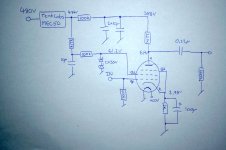
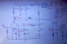
This is my circuit, hope it is readable ?
I think the referance voltage on G2 is to low 61,2V should be 66V
My anode voltage is way to low only 6,4 V should be ~140V
And the cathode voltage is a bit to high 2,78V should be 2,4 volt
What I wrong with my circuit ?
I think the referance voltage on G2 is to low 61,2V should be 66V
My anode voltage is way to low only 6,4 V should be ~140V
And the cathode voltage is a bit to high 2,78V should be 2,4 volt
What I wrong with my circuit ?
Attachments
Looks very neatly put together.. First step I suppose would be to pull the driver tube and measure the open circuit voltages and make sure they make sense.
Then I would double check that the tube pin out is correct in both your schematic and the build. I can't tell you how many times this has tripped me up.
Next measure the voltage across the cathode resistor with the tube installed and calculate the current.
Either measure the screen current directly or subtract the plate current from the cathode current.
What was the target plate current - something on the order of 0.5mA?
You may need to lower the screen voltage slightly and/or increase the effective grid bias by raising the cathode resistor value.
Might be better to do most of this experimentation external to the amp if you have a spare socket and some parts.
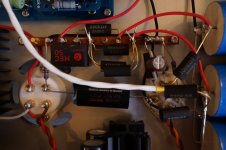
I have changed some resistor values, noticed that the SMD resistors in the original were stacked SMD (parallel) so I changed to 100K before the 2x10u to 50K and the 221K on the anode to 100K, this helped.
I now have 83 volts on the anode, and the input stage works.
But now I have a hum issue, annoying, I think I have been really careful with ground.
I have 1,5v 100HZ on B+ (450volt)
2,7 V 100Hz on the power after the MEC50 module, which is bad (I think) but I have tried B+ on the input stage, and no difference ?
I have 0,7mv AC on the 5V DC heater for 300BXLS
2,5mV on the 20V DC heater for C3m
Any advice on what my next step could be ???
Thanks
I am glad to know you solve the problem, you have to do DC operate for the filament, its seems that it is the HV supply problem, do you mind sharing the whole circuit diagram and power supply with us ?
PS: how many current on anode right now after you have changed the resistor value?
PS: how many current on anode right now after you have changed the resistor value?
Hi I tweaked the resistors a little more, with better result.
I still have the hum problem, but the input stage is running with desired levels.
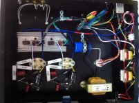
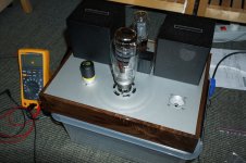
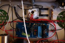
Here are schematics with measurements and a few pictures of the amp.
Ideas for fighting the hum problem are very welcome
Thanks
I still have the hum problem, but the input stage is running with desired levels.
Here are schematics with measurements and a few pictures of the amp.
Ideas for fighting the hum problem are very welcome
Thanks
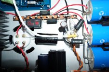
Attachments
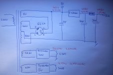
1.) I think e-choke does not work perfectly.
461V (4.7V AC) -> e-choke -> 458V (4.3V AC).
4V difference too low, and PSRR only 0.77dB!
In my e-choke simulation the difference is about 28V (at 80mA), and PSRR is 42dB.
2.) Tentlabs wrote:
Mini Electronic Choke
"The MECs .... offer up to 60dB supply ripple reduction."
Hmmm....
461V (4.7V AC) -> e-choke -> 458V (4.3V AC).
4V difference too low, and PSRR only 0.77dB!
In my e-choke simulation the difference is about 28V (at 80mA), and PSRR is 42dB.
2.) Tentlabs wrote:
Mini Electronic Choke
"The MECs .... offer up to 60dB supply ripple reduction."
Hmmm....
Attachments

- Status
- This old topic is closed. If you want to reopen this topic, contact a moderator using the "Report Post" button.
- Home
- Amplifiers
- Tubes / Valves
- Yamamoto 09S 300B SE Amp Problem