Where is he substituting the LED? for a cathode resistor?
I think yes.
oh oh, Ive seen this schematic before,
and he's driving the 6922 too hard: taking it over its wattage rating.
But others have pointed out that there is nothing really to gain from that, except shortened tube life.
Wich B+ do you recommend?
Do you change something in the schematic (resistors or capacitors values)?
Hello,
I am in agreement with SY the SRPP is very sensitive to load impedance. Where you take the output of the series arrangement shown will make the circuit no longer SRPP. Move the output to pin number 6. The gain will be ½ the mu of the triode at the operational point of B+/2 for each triode with a cathode resistor of 150R. A gain of ~15 is still way high in my view. Roll in a 12AU7 and see how you like that.
edit: remove the cathode bypass capacitor. This appliciation of series triodes has been around from the early 1940's or late 1930's.
DT
With 12AU7 the gain will not be aprox. 15 possible will be aprox. 5?
12AU7 has mu of 17 so gain will be around 8.5 with an unbypassed cathode.
That's 18.5 dBs, not bad at all, how much volts swing?
Wich topology is better SRPP or cathode follower?
My friend is using actually Erno Borbely unbalanced preamp with a gain of 20dB & he's not happy.
Last edited:
SRPP is better as a gain stage, if you need gain. Cathode follower is better as a buffer, if you need a unity-gain buffer. How much gain do you need?Wich topology is better SRPP or cathode follower?
How to do per channel with two cascode 12AUT/ECC82 + half 6DJ8/ECC88 cathode follower? so five tubes (four 12AUT/ECC82 + one 6DJ8/ECC88) per a stereo preamplifier.
ECC82 cascode
An externally hosted image should be here but it was not working when we last tested it.
Any schematic cathode follower ECC88?
What about a cascode with ECC88?
My guess at the gain of the original 6DJ8 circuit in post number 2 is about 24. My guess at the series circuit I proposed with the output moved to pin number 6 of a 6DJ8 is about 15 to 17. My guess at the gain for the 12AU7 in the series circuit I proposed is ~8.5 (also as stated by DF96).
You may want gain and buffer.
DT
You may want gain and buffer.
DT
Last edited:
My guess at the gain of the original 6DJ8 circuit in post number 2 is about 24. My guess at the series circuit I proposed with the output moved to pin number 6 of a 6DJ8 is about 15 to 17. My guess at the gain for the 12AU7 in the series circuit I proposed is ~7.5 (also as stated by DF96).
You may want gain and buffer.
DT
Possibly I need more tubes, I'm not sure because I'm newbie, I suggested more tubes involved for example an input with a twin cascode or SRPP 12AU7 with a cathode follower 6DJ8 to lower the output impedance, total 5 tubes for a stereo preamp.
Either don't use an SRPP or optimize the loading- in a very nice article a few years ago, Merlin Blencowe showed that unlike common-cathode voltage amps, an SRPP will show a distortion null at some (relatively low) value of load. As well, the gain is extremely high for a line amp- he'll probably clip his power amp with the volume control barely advanced.
The schematic has a couple of glaring errors (the input impedance and the bias voltage). You could use a larger cap at the expense of overload recovery time. Or you could substitute a cheap red LED to get near-instantaneous overload recovery, some pretty light, and slightly reduced cost.
Hi Sy
Perhaps you mean this
http://valvewizard2.webs.com/SRPP_Blencowe.pdf
How are the equations of SRPP with LED?
Best regards
Johann
If there is a way to upgrade the schematic your advice will welcome.
Wich value of pot for volume, I have 100K it's ok?
Try an ECC82 instead of ECC88, change 150 ohm resistors by 1.5Kohm resistors, 0.1uF cap by 1uF cap, 150uF bypass cap may be increased to 470uF without problems, +B=350V (well filtered), 100Kohm pot is OK.
With an output impedance in the order of 2.5Kohm and a gain in the order of 10 you don't need anymore.
Float the filaments at say +80V and be happy.
Best regards
Johann
Member
Joined 2009
Paid Member
Hi Merlin,
Let's start with the amplifier.
I see it is a balanced input amplifier, meaning it wants two out-of-phase signals not just a single input signal. If you are going to build a dedicated pre-amplifier to drive it, you could consider a pre-amp with a balanced output. It would be a shame not to take the opportunity to do it as the amplifier is designed to work this way. Running it with a single ended input should also be possible. You might want to confirm with your friend if a balanced input is desired before choosing a design.
Here's a source of information: Aleph-X 100w Amplifier Construction Notes
There's a thread here with a simple schematic but it does require a transformer and good ones are not that cheap:
http://www.diyaudio.com/forums/tubes-valves/92081-balanced-tube-preamp-class-d-power-amps.html
Tubes take time to warm up so you need to consider if you need a 'mute' relay or something between the pre-amp and the amplifier to avoid a turn-on 'thump' from the speakers or just remember to turn on the pre-amp first.
For a single ended preamplifier, like the one you started with, this link may be useful:
DIY 12AU7 Tube preamp
it shows you the design and the results, it also explains how it works which is always nice. The gain looks about right and the performance good. I feel like making one myself")
Let's start with the amplifier.
I see it is a balanced input amplifier, meaning it wants two out-of-phase signals not just a single input signal. If you are going to build a dedicated pre-amplifier to drive it, you could consider a pre-amp with a balanced output. It would be a shame not to take the opportunity to do it as the amplifier is designed to work this way. Running it with a single ended input should also be possible. You might want to confirm with your friend if a balanced input is desired before choosing a design.
Here's a source of information: Aleph-X 100w Amplifier Construction Notes
There's a thread here with a simple schematic but it does require a transformer and good ones are not that cheap:
http://www.diyaudio.com/forums/tubes-valves/92081-balanced-tube-preamp-class-d-power-amps.html
Tubes take time to warm up so you need to consider if you need a 'mute' relay or something between the pre-amp and the amplifier to avoid a turn-on 'thump' from the speakers or just remember to turn on the pre-amp first.
For a single ended preamplifier, like the one you started with, this link may be useful:
DIY 12AU7 Tube preamp
it shows you the design and the results, it also explains how it works which is always nice. The gain looks about right and the performance good. I feel like making one myself
oh oh, Ive seen this schematic before,
and he's driving the 6922 too hard: taking it over its wattage rating.
But others have pointed out that there is nothing really to gain from that, except shortened tube life.

OK this schematic came from here:
DIY 6922 / E88CC Tube preamp
On that page you'll see his loadline for the 6922:

If you plot the Watt Dissipation line over this, you'll see the problem.
The solution is to alter the loadline (by putting a db-pad or volume pot on the output) and also the quiescent-point (idle-current) by adjusting the bias via the cathode resistor, and possibly the voltage.
The 6922 is a great tube, but it is a low-noise fragile signal tube, not meant for this kind of manhandling.
The Dot which represents the idle-spot should be well below the max-dissipation curve.
The voltage swing, which will meander over the line anyway, should never spend more than half its time outside the boundaries.
Although Philips allows 2 watts dissipation / triode,
The Telefunken sets 1.5 watts as the real limit. Obviously we go with the lower rating.
Also, it is generally recommended that your design stay at 70% of max wattage rating for safety and to allow for variation between tubes and brands.
Last edited:
The same as those for a bypassed lower cathode, as the LED has roughly the same AC effect as a bypassed resistor.popilin said:How are the equations of SRPP with LED?
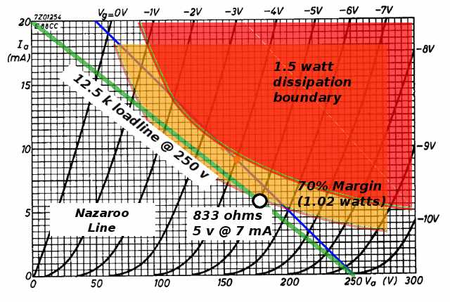
Here's a better loadline and bias0-point for the 6922.
It sits at 70% of the conservative max dissipation (1 watt).
With this bias-point you stay in 70% zone, and tube stays out of trouble most of its life.
The load resistor becomes about 12k5, the cathode resistor is 830 ohms, the bias voltage is -5.
The cathode floats about 150 volts above ground.
The tube coasts in its comfy spot, with very little loss of headroom and great gains in tube longevity.
Attachments
Last edited:
Here's a better loadline and bias0-point for the 6922.
It sits at 70% of the conservative max dissipation (1 watt).
With this bias-point you stay in 70% zone, and tube stays out of trouble most of its life.
The load resistor becomes about 12k5, the cathode resistor is 830 ohms, the bias voltage is -5.
The cathode floats about 150 volts above ground.
The tube coasts in its comfy spot, with very little loss of headroom and great gains in tube longevity.
That's your proposed schematic?
Attachments
- Status
- This old topic is closed. If you want to reopen this topic, contact a moderator using the "Report Post" button.
- Home
- Amplifiers
- Tubes / Valves
- 6DJ8/ECC88-SRPP Tube Preamplifier