Well done, though I must admit I find this quite baffling. If the anode load was say 1 meg and the valve's anode resistance at your operating point was say 2k then the resultant must surely have been less?
As far as I can remember, I had no such trouble with the prototype I built; in those days I had a 'scope and would have seen any extraneous rubbish.
Anyway, happy listening.
P.
Yes 7N7, thats what I thought... Something parallel to 2kohm, whatever it is, shouldnt be able to make the total output impedance make more, only less...
So there must be someting in series with it... Maybe its the negative supply maybe the ccs i dont know....
Not only my measurements confirm it, but also experience... If i put my fingers near the output it started humming more.. The testleads of the multimeter injected so much hum that i had to switch the scope to less sensitive...
But now with the normal ltp, with only a ccs in the tail, the testleads dont matter anymore. No hum. Also my hand doesnt beam hum
 anymore...
By the way, in the wiki article about differential amplifiers and in particular ltp, it says: ltp with active load has high output impedance....
Thanks for al your help though... And the rest of the people who helped.
I will have to design a new pcb, and then to the mechanical part of the dac/preamp.
The wiki text:
The input impedance of the differential pair highly depends on the input mode. At common mode, the two parts behave as common-collector stages with high emitter loads; so, the input impedances are extremely high. At differential mode, they behave as common-emitter stages with grounded emitters; so, the input impedances are low.
The output impedance of the differential pair is high (especially for the improved differential pair from Fig. 3).
The wiki text:
The input impedance of the differential pair highly depends on the input mode. At common mode, the two parts behave as common-collector stages with high emitter loads; so, the input impedances are extremely high. At differential mode, they behave as common-emitter stages with grounded emitters; so, the input impedances are low.
The output impedance of the differential pair is high (especially for the improved differential pair from Fig. 3).
This refers to transistors: "grounded emitter" which I doubt is relevant (I have no understanding of silicon or indeed how one amplifies a current!)
After all our differential pairs have the exact opposite of grounded emitters: cathodes sitting on very high impedances.
P.
Pauldune,
have you ever thought of that you could have had an oscillation problem?
Best regards!
Yes I did, but on my 50Mhz scope wasnt anything visible. I thought that maybe that noise was from oscillation.
But even if, I doubt it could make output impedance higher. And distortion figures were superb; normally you would expect some residual spikes on the fft.
By the way I just measured output impedance on the normal 1 ccs LTP, with 15K plate resistors in stead of 4k7, and output impedance rose from 3K to 9.1K.
Since it sounds so good, i'm gonna use the normal LTP with 4k7 plate resistors.
Paul
I think a CCS (not a current mirror as in the Wikipedia article) in the anode circuit is a wrong concept. A CCS does not allow any change in the anode current, which would be necessary for amplification....
Well as I wrote earlier, I have done this and it worked very well - also see Valve Amplifiers by Morgan Jones (3rd Ed.) where he has done the same with ECC83. Mind you the active anode loads would not have had the same effective impedance as the cascode sinks... Just think of the anode loads as an enormous resistor - it is after all a voltage amplification stage.
Last edited:
Hi Paul
It may seem a little counter intuitive, but.....
If you want a low output impedance from a LTP, it's no good having equal loads on both anodes. If you want a low output impedance from one anode, then the other anode has to be connected to a low load impedance.
Have a look at the simple circuit below.
Answers:
Applying 10V RMS to V2's anode causes a voltage swing on V1's anode of a bit less than that - maybe 8V RMS.
Now what about the signal current?
There will be about 100uA flowing through R2, but how much flows through V2? That has to be the same as the current through V1, which is the same as the current through R1 i.e. about 80uA.
So the total signal current from the voltage source through the capacitor is about 180uA RMS, meaning that the output impedance of the circuit is about 55K.
If the anode of V1 is tied to ground with a capacitor, the output impedance is much lower - closer to what you'd expect. In your circuit, maybe you could rewire the regulator chip connected to the first anode so that it holds the anode at a constant voltage. Then you could get a low output impedance from the 2'nd anode.
Cheers - Godfrey
Attachments
Hi Paul
It may seem a little counter intuitive, but.....
If you want a low output impedance from a LTP, it's no good having equal loads on both anodes. If you want a low output impedance from one anode, then the other anode has to be connected to a low load impedance.
Have a look at the simple circuit below.
Answers:
Applying 10V RMS to V2's anode causes a voltage swing on V1's anode of a bit less than that - maybe 8V RMS.
Now what about the signal current?
There will be about 100uA flowing through R2, but how much flows through V2? That has to be the same as the current through V1, which is the same as the current through R1 i.e. about 80uA.
So the total signal current from the voltage source through the capacitor is about 180uA RMS, meaning that the output impedance of the circuit is about 55K.
If the anode of V1 is tied to ground with a capacitor, the output impedance is much lower - closer to what you'd expect. In your circuit, maybe you could rewire the regulator chip connected to the first anode so that it holds the anode at a constant voltage. Then you could get a low output impedance from the 2'nd anode.
Cheers - Godfrey
I'm sorry,
I try to understand what you have written, but i fail to grasp it.
As you descibe it the current through v1 and v2 is equal, but in an ltp it is just the opposite. Current through v1+current through v2=tail current.
So if Iv1 grows larger, Iv2 declines, and vv.
Only thing to consider is the current that leaks away to the output... Or am I mistaken?
I don't understand it either, Gain in a differential pair is found between the anodes - or a sort of sum and difference if you like - as Anode 1 goes "up" anode 2 goes "down" so to speak, A theoretically perfect diff pair will have infinite impedance in the tail, so for perfect operation there will be no (ac) current there.
As for the question : "what current is flowing here" I would expect only the current necessary to drive the capacitance of the next stage.
As for the question : "what current is flowing here" I would expect only the current necessary to drive the capacitance of the next stage.
Low impedance output means "ability to produce more current".
And thus, since the total current is forced constant by the CCS in the cathodes, all the current you try to extract from one output must inevitably be "robbed" from the other one.
So the lowest output (internal) impedance at one side is obtained when the load of the other side is null.

Yves.
And thus, since the total current is forced constant by the CCS in the cathodes, all the current you try to extract from one output must inevitably be "robbed" from the other one.
So the lowest output (internal) impedance at one side is obtained when the load of the other side is null.
Yves.
That's the key. Because of the CCS, there can be no common-mode output current, which effectively means that common-mode output impedance is infinite. OTOH, the differential output impedance = 2* Rplate as you'd expect.Gain in a differential pair is found between the anodes...
So balanced output from a LTP is similar to balanced output from a transformer. If one side of the output is disconnected (no load), then no current can flow from the other output.
Low impedance output means "ability to produce more current".
And thus, since the total current is forced constant by the CCS in the cathodes, all the current you try to extract from one output must inevitably be "robbed" from the other one.
So the lowest output (internal) impedance at one side is obtained when the load of the other side is null.
Yves.
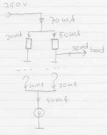
I'm sorry, I disagree.
The cathode ccs ONLY forces the cathode current.
The powersupply can deliver more current into the load.
Like in the extreme example attached...
Or is that not what you mean?
Attachments
That's the key. Because of the CCS, there can be no common-mode output current, which effectively means that common-mode output impedance is infinite. OTOH, the differential output impedance = 2* Rplate as you'd expect.
So balanced output from a LTP is similar to balanced output from a transformer. If one side of the output is disconnected (no load), then no current can flow from the other output.
I'm sorry Godfrey,
I can't agree.
After all, i have (in the 1 ccs version) nothing connected to the negative output, and I have a measured output impedance of 4K, with 4.5K plate resistors. So there is current flowing from the output...
With 15K resistors I have 9K output impedance; so your "2x Rplate" statement can't be true either.
Or maybe I'm missing it completely
Yes, the sum of the cathode currents.I'm sorry, I disagree.
The cathode ccs ONLY forces the cathode current.
Would be true if the load was a constant current sink, in fact the current sunk by the load depends on the voltage applied to it and on its own resistance or should I say its impedance since it is probably AC coupled, and on the voltage applied between the grids wich "unbalances" the differential amplifier but the sum of the cathodes currents remains the same.The powersupply can deliver more current into the load.
Like in the extreme example attached...
The current into the load cannot swing more than the ccs in the cathodes allows.
I mean that we need that the current must swings into the load, consider the case where the load is sourcing 30mAOr is that not what you mean?
The right size of the diff amp can't ignore what the left side is doing . . . or it's no longer a differential amplifier.
Yves.
Sorry. By "Rplate", I meant the output impedance of the tube itself, not the external resistor. In other words, what you were referring to here (I think):
That is what I meant by Rplate. What is the correct terminology?The plate resistance of a d3a is 1.9Kohm.
Sorry. By "Rplate", I meant the output impedance of the tube itself, not the external resistor. In other words, what you were referring to here (I think):
That is what I meant by Rplate. What is the correct terminology?
In England, "Anode Resistance" - the internal resistance of the valve itself - dependent upon the chosen operating point.
Output resistance is another thing altogether of course. There is often some confusion about this it seems to me - output impedance implies a reactive component, such as Miller capacitance or input capacitance in the next stage, reactance of chokes etc.
Last edited:
Sorry. By "Rplate", I meant the output impedance of the tube itself, not the external resistor. In other words, what you were referring to here (I think):
That is what I meant by Rplate. What is the correct terminology?
I did understand that correct; but Zout can't be 2x Rplate; because if the anode resistors are 15K, the output impedance rises to much more than 2x Rplate: 9K. (measured)
That I do understand;Yes, the sum of the cathode currents.
Would be true if the load was a constant current sink, in fact the current sunk by the load depends on the voltage applied to it and on its own resistance or should I say its impedance since it is probably AC coupled, and on the voltage applied between the grids wich "unbalances" the differential amplifier but the sum of the cathodes currents remains the same.
The current into the load cannot swing more than the ccs in the cathodes allows.
I mean that we need that the current must swings into the load, consider the case where the load is sourcing 30mA
The right size of the diff amp can't ignore what the left side is doing . . . or it's no longer a differential amplifier.
Yves.
But still, In the first build of the 3 CCS version, I attached an 100K load to the output of the negative output. Plus on both sides the 100K current spilling resistors, wich were also connected from anode(plate) to ground.
With al this, output impedance was 30K.(measured)
When I lowered the 100K's to 47K, nothing changed!
When I took out the top ccs's and removed the load from the - output, and removed the current spilling resistors, and made it a normal LTP with 4.5K anode resistors, THEN the output impedance dropped to 3K.
In experimentation, I removed the current spilling resistors from the 3 ccs version, and other then making it very hard to tune (a very slight movement of the 10 turn potmeter made the plate voltage jump up or down) it changed almost nothing!
So wile I understand most of what you are saying, my expierence tells otherwise... or at least it looks that way to me.
I really appreciate all the education you guys out there are trying to give me!
- Status
- This old topic is closed. If you want to reopen this topic, contact a moderator using the "Report Post" button.
- Home
- Amplifiers
- Tubes / Valves
- I need help with ccs based LTP