Let me state that the internal impedance is as low as you can swing current in a given load (assuming for simplicity a given voltage swing).That I do understand;
But still, In the first build of the 3 CCS version, I attached an 100K load to the output of the negative output. Plus on both sides the 100K current spilling resistors, wich were also connected from anode(plate) to ground.
With al this, output impedance was 30K.(measured)
When I lowered the 100K's to 47K, nothing changed!
This can be writen as Zout = Vout / Iout.
Yes, in this situation, the only current swing you may obtain is the one allowed thru the 100 or 47K resistor.
And, still for the same given voltage, it's obvious than you can draw more current thru 3K than thru 100K.When I took out the top ccs's and removed the load from the - output, and removed the current spilling resistors, and made it a normal LTP with 4.5K anode resistors, THEN the output impedance dropped to 3K.
In experimentation, I removed the current spilling resistors from the 3 ccs version, and other then making it very hard to tune (a very slight movement of the 10 turn potmeter made the plate voltage jump up or down) it changed almost nothing!
So wile I understand most of what you are saying, my expierence tells otherwise... or at least it looks that way to me.
I really appreciate all the education you guys out there are trying to give me!
Lets assume you are right; what are you trying to tell me Yves?
That if I load it with a low resistance load I get a lower output impedance?
And that it can actualy deliver more current into that load?
Let me ask you in another way: what, in your opinion, should I change in my schematic to get a lower output impedance?
That if I load it with a low resistance load I get a lower output impedance?
And that it can actualy deliver more current into that load?
Let me ask you in another way: what, in your opinion, should I change in my schematic to get a lower output impedance?
You really should study Valve Amplifiers (3rd Ed.) by Morgan Jones. As I quoted earlier in this thread, when only one output of a differential pair is loaded then output resistance rises. When the differential pair is operating in balnced mode (as it is designed and supposed to do) Jones states that the output resistance is identical to that of a normal single common cathode amplifier stage. He goes on to demonstrate mathematically that when the output is unbalanced (only one terminal loaded) then r out is approximately = RL/2, which with an active load would be high indeed. - could be hundreds of k ohms.
Moral: do not overdrive your diff pairs.
Moral: do not overdrive your diff pairs.
Give the circuit a chance to work. Get rid of the two top CCS´s and replace them with gyrators!
I checked my gyrator box, and its empty!But seriously, I know thats probably a good idea, but i want (desperately) to know what is going on with my schematic...I might learn somthing from it...
Now that is interesting; if only I had the book....You really should study Valve Amplifiers (3rd Ed.) by Morgan Jones. As I quoted earlier in this thread, when only one output of a differential pair is loaded then output resistance rises. When the differential pair is operating in balnced mode (as it is designed and supposed to do) Jones states that the output resistance is identical to that of a normal single common cathode amplifier stage. He goes on to demonstrate mathematically that when the output is unbalanced (only one terminal loaded) then r out is approximately = RL/2, which with an active load would be high indeed. - could be hundreds of k ohms.
Moral: do not overdrive your diff pairs.
I spent all my money on CCS's
RL/2 that is interesting...
I think i'm going to buy the book as soon as possible!
It is as godfrey says. With all high impedance (even a gyrator, Lars), the circuit will act like a transformer with high impedance connections to ground. To get low impedance into a single ended load, you need a load on the other side to react against. It only has low differential output impedance. The common mode output impedance is high. Differential impedance is (ra + ra) || (Ri + Ri). Common mode impedance is (ra || ra). Where ra is load resistance and Ri is internal resistance of the tube. Spiller R and load R are in parallel.
You probably need to balance the 2 sides of the LTP to get good CMRR relative to the input, so low value resistors are about as good as it gets I think. Hmmm maybe not. I would try connecting a capacitor from the unused output to ground with the high value spill resistors. I think the tail CCS will give you good input CMR.
You probably need to balance the 2 sides of the LTP to get good CMRR relative to the input, so low value resistors are about as good as it gets I think. Hmmm maybe not. I would try connecting a capacitor from the unused output to ground with the high value spill resistors. I think the tail CCS will give you good input CMR.
Last edited:
Yes I think that would be a good idea; there is a fourth edition supposed to be out now; it is expensive. I think RL/2 would be an extreme example with a diff pair well into distress.
I can send you a rough sketch of my active-loaded diff pair with cathode followers; I cannot post it here (not my computer)
Meanwhile please read this thread:
I can send you a rough sketch of my active-loaded diff pair with cathode followers; I cannot post it here (not my computer)
Meanwhile please read this thread:
Could this be the reason that some tube LTPs have one anode connected to B+, and the unbalanced output is taken from the other anode?
Yes. I think people are used to looking at phase splitter/inverter circuits. This is the opposite; differential to SE.
... I would try connecting a capacitor from the unused output to ground with the high value spill resistors. I think the tail CCS will give you good input CMR.
Now that sounds like something to try; dc high impedance, ac low impedance on the unused output...
I'm going to post back here what the outcome will be...
it will take a few days i'm afraid....
Could this be the reason that some tube LTPs have one anode connected to B+, and the unbalanced output is taken from the other anode?
Oshifis,
Do you have an example? (link)
Paul
Paul, you mentioned earlier that the circuit below has an output impedance of about 30K. Notice that that is roughly equal to the parallel combination of the 3 resistors I've circled in blue.
What I'm suggesting is that if you replace the middle one with a wire link, the output impedance will be much lower. Why not try it?
Cheers - Godfrey
What I'm suggesting is that if you replace the middle one with a wire link, the output impedance will be much lower. Why not try it?
Cheers - Godfrey
Attachments
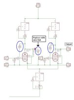
Paul, you mentioned earlier that the circuit below has an output impedance of about 30K. Notice that that is roughly equal to the parallel combination of the 3 resistors I've circled in blue.
What I'm suggesting is that if you replace the middle one with a wire link, the output impedance will be much lower. Why not try it?
Cheers - Godfrey
Godfrey, that is exactly what Michael proposed; I couldnt leave it alone so I just tried it a few minutes ago:
Gain goes up like crazy AND output impedance drops = 5Kohm!!!Gain is almost double that of the previous attempt and almost 3 times the standard 1 ccs version!
Attachments
Now off to connect it to my stereo: wish me luck that it is not noisy and/or hummy...
Oh and somthinge else: its still a great balanced/summing amplifier. Both signals + and - are equally represented. when I shortcircuit one of them, signal dropped. Not exactly in half, but equally on both signals.
Oh and somthinge else: its still a great balanced/summing amplifier. Both signals + and - are equally represented. when I shortcircuit one of them, signal dropped. Not exactly in half, but equally on both signals.
Last edited:
OK! Noise and hum are a bit more than the normal 1 ccs version, but only audible at less than 30cm from the speaker.
Its 10 times less than the previous attempt with the 3 ccs's, so that is a whole lot improvement.
I'm going to convert the second channel too and then listen.
Its 10 times less than the previous attempt with the 3 ccs's, so that is a whole lot improvement.
I'm going to convert the second channel too and then listen.
Listened to it a few songs... It works ok, sounds good too, but...
I had the impression that the normal 1ccs version sounded better.
I just tried some other tubes, russian e180f, 6jk9p (strange sign looks like j and k combined) but altough it sounded ok, d3a where better.
I cannot really explain what was better on the normal 1ccs version of the ltp, but it sounded more relaxed AND detailed at the same time.
Can be just fatigue now, so i will listen a few days to it before judging...
Another thing, the 3ccs versions are all extremely microphonic, much more then the 1ccs.
1 slight touch to the tube give a loud chiming noise for a few seconds.
I thought that maybe an explanation could be that there is an extra capacitor in the signal path now, but thats not true.
In the standard version, there is the latest powersupply capacitor wich is in the signalpath, it has more or less the same function, to provide low impedance path to ground for ac signals. In the 3 ccs version, the powersupply is well isolated from signal currents, so there is no signal flowing there.
But there is the cap to short the -output to ground... I put in a 1uF mkp; the 0.1 started damping at ~200 Hz.
Probably even more is wanted if you want to do it right, i think 10uF.
So why the standard ltp sounds better remains a mystery to me...
Last edited:
Hooray! (It's always a slight relief when theory and practice decide to agree with each other).
Re your other comments:
I expect each current source adds some noise so the fewer of them, the better. They're probably not very linear either, and the ones at the top have a significant voltage swing on them, so they probably introduce some distortion.
Voltage swing is normally less than 3v pp.
It could be noise from ccs's.
The ccs's should be quite linear... But to be sure i have to do some measurements.
Another thing:as i increased load, i could see some phase shift increasing.
Listened to it a few songs... It works ok, sounds good too, but...
I had the impression that the normal 1ccs version sounded better.
I just tried some other tubes, russian e180f, 6jk9p (strange sign looks like j and k combined) but altough it sounded ok, d3a where better.
I cannot really explain what was better on the normal 1ccs version of the ltp, but it sounded more relaxed AND detailed at the same time.
Can be just fatigue now, so i will listen a few days to it before judging...
Another thing, the 3ccs versions are all extremely microphonic, much more then the 1ccs.
1 slight touch to the tube give a loud chiming noise for a few seconds.
Microphony can sometimes be indicative of oscillation and oscillation can be quite surprising. I once had a line stage with 6SN7s with cathode followers. A friend had better test gear than I and found that it was going off at 2.4MHz!
- Status
- This old topic is closed. If you want to reopen this topic, contact a moderator using the "Report Post" button.
- Home
- Amplifiers
- Tubes / Valves
- I need help with ccs based LTP