I have an old beater ST70 that I keep experimenting with. I've stripped it down, once again (output tube sockets wore out). So I have a new project.
In honor of the late Arthur Loesch, I'm going to try to make this a "dual-diff" push-pull triode amp, sort of like the PP-6B4G amp from the "No Stone Left Unturned" article in an early issue of Sound Practices. It's also a lot like the 6L6 AB2 amp in a thread on this forum. But I'll be happy with 10 weenie little class A watts per side.
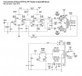
I've attached the proposed schematic below. It's very simple because I need to pack a lot of tube sockets in this very small ST70 chassis. (I'll be making a plate to go where the original PCB went. Point-to-point wired...)
In order to keep the current draw within reasonable limits, I plan on using 6L6GC's in triode instead of EL34's for the finals. That should save a lot in heater current. I figure I'll need it, because each 5687 will draw as much heater current as a 6L6.
I have solid-state rectification in the chassis already. So I won't be using the 5VAC winding. I hope that saves more stress on the old Dyna power transformer.
My major concern is exceeding the heater-to-cathode voltage limits of the 5687's at turn-on. The 5687 grids are DC-coupled from the 6DJ8 plates. I put in a pair of diodes from the 5687 cathodes to grids, so that the cathodes will be kept from going way up to the B+ while the tubes are warming up. Did I do that correctly?
I also floated the heater windings on +45VDC. Maybe that's not necessary. The original has the heater windings blocked from ground by a 20nF 1kV ceramic capacitor. Maybe that's all that's necessary? That part is still wired up.
Thanks for any advice on this (I'm afraid I'm just good enough at this to be really dangerous!).
--
In honor of the late Arthur Loesch, I'm going to try to make this a "dual-diff" push-pull triode amp, sort of like the PP-6B4G amp from the "No Stone Left Unturned" article in an early issue of Sound Practices. It's also a lot like the 6L6 AB2 amp in a thread on this forum. But I'll be happy with 10 weenie little class A watts per side.
I've attached the proposed schematic below. It's very simple because I need to pack a lot of tube sockets in this very small ST70 chassis. (I'll be making a plate to go where the original PCB went. Point-to-point wired...)
In order to keep the current draw within reasonable limits, I plan on using 6L6GC's in triode instead of EL34's for the finals. That should save a lot in heater current. I figure I'll need it, because each 5687 will draw as much heater current as a 6L6.
I have solid-state rectification in the chassis already. So I won't be using the 5VAC winding. I hope that saves more stress on the old Dyna power transformer.
My major concern is exceeding the heater-to-cathode voltage limits of the 5687's at turn-on. The 5687 grids are DC-coupled from the 6DJ8 plates. I put in a pair of diodes from the 5687 cathodes to grids, so that the cathodes will be kept from going way up to the B+ while the tubes are warming up. Did I do that correctly?
I also floated the heater windings on +45VDC. Maybe that's not necessary. The original has the heater windings blocked from ground by a 20nF 1kV ceramic capacitor. Maybe that's all that's necessary? That part is still wired up.
Thanks for any advice on this (I'm afraid I'm just good enough at this to be really dangerous!).
--
Attachments
I won't argue with your calculations of heater current, but remember besides the 4 each 6CA7 and the 2 each 7199, the ST70 power transformer had heater current for four more 12AX7's. That is two PAS1 preamps worth.
Be sure to terminate the unused 5 VAC heater winding with 1k ohm 1 watt resistor to prevent excessive voltage from building up.
Be sure to terminate the unused 5 VAC heater winding with 1k ohm 1 watt resistor to prevent excessive voltage from building up.
Be sure to terminate the unused 5 VAC heater winding with 1k ohm 1 watt resistor to prevent excessive voltage from building up.
Hey thanks, I hadn't thought of that. How would I terminate those windings? You mean put a 1k 1W resistor from each yellow lead to ground?
--
Last edited:
Quote:
Originally Posted by indianajo
Be sure to terminate the unused 5 VAC heater winding with 1k ohm 1 watt resistor to prevent excessive voltage from building up.
I think I'll use that 5VAC winding to make a simple 6VDC supply for the driver tubes' heaters. Why not? A 5A Schottky diode, a 10,000uF 16V 'lytic and it'll be good enough, I'm sure. Not optimal, but oh well...
--
Does anyone know if the resistor value matters for triode wiring an EL34 or 6L6? (Resistor placed between screen grid and plate/anode.)
I don't have four of anything less than 1k ohms in 1W (metal oxide). I see that Eli D uses 1k ohms (carbon comp) there in the El Cheapo (6AQ5). But you usually see 100R or 220R, 1W.
I think the resistor is only there to inhibit the screen grid from drawing current. So I'd think 1k would work fine there. I'd also think a 1/2 watt resistor would be fine there, but when I've used them in that location, they always look like they're getting heated up too much. Never had one fail, though.
Am I missing something?
(Sorry, I searched but wasn't able to find a discussion on this particular subject...)
--
Well, I don't know the answer but......
FWIW, Poindexter uses either 332 ohm or 150 ohm R (and a diode in series with the R) in the triode wired EL34 MM depending on which schemo you find.
I think you may struggle getting 6.3VDC out of a 5V winding.......it may be tough even with a 6.3V winding to get clean DC.
Great thread, BTW
Have you thought about throwing some powerdrive MOSFETs in there?
FWIW, Poindexter uses either 332 ohm or 150 ohm R (and a diode in series with the R) in the triode wired EL34 MM depending on which schemo you find.
Yeah, that's what I expected. I've seen 100R, 150R, 220R, now 330R in the MM. Maybe I remember 470R in some amp somewhere. But the only one I've seen with 1k between plate and screen is Eli's El Cheapo with 12AQ5's.
I think you may struggle getting 6.3VDC out of a 5V winding.......it may be tough even with a 6.3V winding to get clean DC.
I figure if I get 6VDC, I'll be OK. That would be only 5% low, which would make the tubes run cooler. There was evidence (from a Norman Crowhurst article?) that slightly undervoltaging the heaters makes indirectly-heated tubes last longer... Unless that has been refuted somewhere.
If I don't get 6V, I'll rip it out and feed the 6DJ8's and 5687's from the 6.3VCT windings.
Have you thought about throwing some powerdrive MOSFETs in there?
Yes, but there's very little space in a Dyna ST70. Maybe if I used a 12AT7 as a LTP phase splitter with powerdrive MOSFETs to the EL34 grids... But I'm not sure I'd get enough voltage swing in, even from a 430V B+. I figure a 12AT7 as LTP phase splitter (unbalanced input, balanced P-P output) will only yield a gain of about 30, and I'd expect the 12AT7's Vgk to only be about 1.5V. So figure only a little more than 35Vpk output, which wouldn't leave enough room for NFB. I figure there's no way the stock ST70 OPT's are going to be long-term satisfying without a little NFB. I figure I'll need 5 or 6dB NFB.
I've built this dual-LTP driver before. It really sounds great when it works. It does tend to oscillate if not laid out well.
I spent a couple hours planning the layout for the dual-LTP driver. It's going to be tight, but I think I can make it work.
I have piles of 1980s vintage Philips ECG 5687WB and 6922 tubes around. I figure I should use them. I figure I'll get a gain of about 14 from the first stage (unbal in/bal out), and about 12 from the second stage (bal in/bal out). That'll give me gobs of voltage swing to eat up with NFB. Maybe Schade?
--
Last edited:
The dynakit PAS2 preamp runs the 12AX7's at 12 VDC. I've been running it since 1982 with two silicon diodes instead of the selenium, drops another volt off. Two of my 12AX7 in the PAS2 are 51 years old, and I replaced the other two in 1974 for popping, probably caused by leftover flux on the PCB and humidity, not the tubes.I figure if I get 6VDC, I'll be OK. That would be only 5% low, which would make the tubes run cooler. There was evidence (from a Norman Crowhurst article?) that slightly undervoltaging the heaters makes indirectly-heated tubes last longer... Unless that has been refuted somewhere.
--
The 5AR4 is a filament current hog, getting 6VDC out for a measly signal tube should be easy. Use schottky diodes.
Last edited:
12VDC is less than 5% under the nominal 12.6V. So not a problem at all.
According to Valve Wizard, heaters can be run up to 10% below nominal voltage with no audible effects, and increased tube life:
The Valve Wizard
There's some other cool stuff in there too...
--
I've been puzzling over how to cram all the power supply parts into that little ST70 chassis. The eternal problem, down through the ages...
Friday the Thirteenth!
Spent some time today fashioning a plate from aluminum sheet and drilling holes. All went fine until I checked the holes I'd punched for the 9-pin tube sockets. They're too small! It seems I have the wrong size Greenlee chassis punch. I hadn't used it in years, and now I know why. It's an 11/16" diameter hole punch. 1/16" too small.
Any ideas how to enlarge the diameter of a round hole by 1/16", without killing myself?

Fortunately, the hole doesn't have to look good. The hole's edges will be covered up by the tube socket's mounting ring.
--
Spent some time today fashioning a plate from aluminum sheet and drilling holes. All went fine until I checked the holes I'd punched for the 9-pin tube sockets. They're too small! It seems I have the wrong size Greenlee chassis punch. I hadn't used it in years, and now I know why. It's an 11/16" diameter hole punch. 1/16" too small.
Any ideas how to enlarge the diameter of a round hole by 1/16", without killing myself?
Fortunately, the hole doesn't have to look good. The hole's edges will be covered up by the tube socket's mounting ring.
--
")
Spent some time today fashioning a plate from aluminum sheet and drilling holes. All went fine until I checked the holes I'd punched for the 9-pin tube sockets. They're too small! It seems I have the wrong size Greenlee chassis punch. I hadn't used it in years, and now I know why. It's an 11/16" diameter hole punch. 1/16" too small.
Any ideas how to enlarge the diameter of a round hole by 1/16", without killing myself?
Fortunately, the hole doesn't have to look good. The hole's edges will be covered up by the tube socket's mounting ring.
--
Your looking at it wrong. You should be happy, you didn't punch them to big!
Well, being frustrated by not getting the driver circuit plate done today, and in the spirit of it being Friday the Thirteenth and all, I had to ask myself what else could go wrong. So I looked at the circuit, looked at the little ST70 chassis, thought about all that heater and plate current drawn by 5687's, and began to fear for the longevity of the old Dyna power transformer.
The total filament draw from the ST70's original four EL34's and pair of 7199's was 6.9A.
Those same four EL34's with a pair of 6DJ8's and a pair of 5687's would draw a whopping 8.4A through the heaters. I had the 6DJ8 and 5687 plate currents set at 6mA and 12mA per triode, respectively. That would be a lot bigger current load on the transformer than stock. And yes, I did plan on rectifying the 5VAC winding for the driver stage heaters, but I think the final amp would still run at too high a temperature.
I think I'd better back all that off a bit... So I looked at what different tubes I could use that wouldn't draw so much current, both from the heaters and through the plates.
Somewhere along the way, I got a few 6GU7's, which are sort of like 6CG7 but with about half the rp and twice the gm. Drew some loadlines and this looks like it could be a winner.
Eli Duttman really seems to like the 12AT7 as a high gain cathode coupled phase splitter, so I drew some loadlines for that with as low a plate voltage as I felt I could get away with. Looks really good, and I have dozens of nice ones from my Fender amp days.
The 6GU7 heater draws only 600mA per tube, and the 12AT7 heater draws 300mA (at 6.3V).
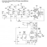
So I figured out some things, added some tweaks, and here's what I have for the proposed circuit (attached).
--
The total filament draw from the ST70's original four EL34's and pair of 7199's was 6.9A.
Those same four EL34's with a pair of 6DJ8's and a pair of 5687's would draw a whopping 8.4A through the heaters. I had the 6DJ8 and 5687 plate currents set at 6mA and 12mA per triode, respectively. That would be a lot bigger current load on the transformer than stock. And yes, I did plan on rectifying the 5VAC winding for the driver stage heaters, but I think the final amp would still run at too high a temperature.
I think I'd better back all that off a bit... So I looked at what different tubes I could use that wouldn't draw so much current, both from the heaters and through the plates.
Somewhere along the way, I got a few 6GU7's, which are sort of like 6CG7 but with about half the rp and twice the gm. Drew some loadlines and this looks like it could be a winner.
Eli Duttman really seems to like the 12AT7 as a high gain cathode coupled phase splitter, so I drew some loadlines for that with as low a plate voltage as I felt I could get away with. Looks really good, and I have dozens of nice ones from my Fender amp days.
The 6GU7 heater draws only 600mA per tube, and the 12AT7 heater draws 300mA (at 6.3V).
So I figured out some things, added some tweaks, and here's what I have for the proposed circuit (attached).
--
Attachments
Last edited:
If your top plate is thick, enlarge the hole from both sides with the step bit.
Thanks. I'll need to get one tomorrow evening (local tool store is open til 9pm). I've never used one before, so I'll need all the advice I can get. I only have a hand drill. The plate is aluminum, fortunately not steel. It is a little on the thick side, a hair less than 3/32".
I probably won't get to work on the plate again until Sunday.
--
I've never used one before, so I'll need all the advice I can get. I only have a hand drill.
--
The step bit is your weapon of choice. Just take your time and hang on to the plate..and the hand drill...and go one step at a time. With .093" stock, you may get a clean hole going from one side, although you can come in from the other side once drilled to minimize the taper.
- Status
- This old topic is closed. If you want to reopen this topic, contact a moderator using the "Report Post" button.
- Home
- Amplifiers
- Tubes / Valves
- Dyna ST70 to Dual-differential EL34 triode amp project