Didn't know you could buy such things as current regulator diodes with a 1N number.
Those CRD's aren't worth using anymore. I got a bagful back in the 1990's, because I didn't know any better. I only used them in this amp because I'm clearing out my parts drawers. I'd use an LM334 if I didn't already have these.
--
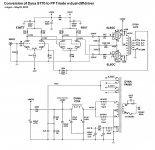
I updated the schematic from April 17's post. It should show the corrections. It also shows the new feedback resistor value (see below).
It also shows some of the updates that resulted from last night's testing. And speaking of testing...
The amp makes 10 watts per side before clipping. It clips very symmetrically, which is nice, with no crossover notch at all.
I listened to it originally with a 33k feedback resistor. It turns out that was 12dB of NFB. No wonder the amp sounded so squeaky clean, but not as "involving" as I like. But the input sensitivity was good for playing sources straight into an attenuator and direct to the power amp (no preamp needed).
Open loop, the amp got to its 10 watts out with a little more than 150mV pk input. I added 5dB NFB to get that to 300mV to full power. This was measured on a nice analog RMS voltmeter with decibel scale.
Open loop bandwidth was -2dB at 18Hz and 34kHz (approximately, I was a little rushed). Bandwidth improved to -2dB at 11Hz and 170kHz after adding the 5dB NFB.
Square waves looked just OK open loop. Perfectly fine 1kHz square wave at 1W output, and just slightly rounded leading edge at full power out (open loop). After the feedback, the 1kHz square wave looks fine all the way to full power.
Full power 10kHz square wave still looks recognizable w/o NFB. Looks better w/ NFB, but still rounded off a hair, and with a hint of overshoot peak right at the leading edge. But really not too shabby for what it is. I forgot my camera, so no pictures. I'm sorry about that.
I looked for oscillations but didn't find any. That was on a 60MHz scope. I think the amp's A-OK.
The power supply rails have like 10mV of ripple on them, but the diff-pairs don't seem to care. The amp is very quiet, the closest to noise-free of any amp I've built. I'm really happy about that.
There's just a little 60Hz switching noise on the heater windings. The 10nF caps bypassing the 6.3V windings to ground didn't kill it off, but it did reduce it some.
My only gripe is that the amp is a bit too sensitive for my stepped attenuator. My attenuator has very coarse steps (2dB). In other words, it gets really loud at low settings. I think I'm going to try changing the input LTP to a 6FQ7. A 6FQ7 should give me about half the gain of a 12AT7, so a -6dB difference in input sensitivity, correct?
--
I'll be able to listen to it at a reasonable level later today. I trust it well enough to go into the main system (Pioneer PD-D6-J SACD player, Intact Audio inductive attenuator, Snell Type J/III speakers).
--
Well, thanks!
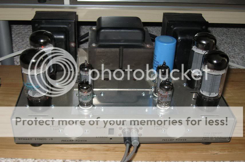
I spent the day listening while working at the computer, of course beset by gremlins. The RCA cable you see in the picture decided to fail this afternoon, making a horrific buzz. I thought, "Oh no, what broke now?" But it was just the cable.
The amp's sound is pretty nice. It's nice and rich, not too lean. I like that. It might sound a bit too "boisterous" for my room. I might add a few dB more NFB, to bring the gain back into line with my attenuator's taper. This is my first time giving gNFB a fair chance. It's not as evil as the triode purists made it seem. Just don't add too much, that's all...
I tried a little experiment and put a pair of 12AU7's (oh no!) in place of the 12AT7's. The 12AU7's mu of about 20 is a third of the 12AT7's, so I guess the gain in the LTP phase splitter circuit would be about 7, instead of the 12AT7's measured in-circuit gain of 21. The 12AU7's sounded good in there too.
Maybe I should rewire the heaters to the front sockets and put a pair of 6FQ7's in there. The op point would be a little less than optimal, but there should still be enough gain. Open loop, it might take more like 850mV peak input to reach full power, instead of the approx 200mV I measured with the 12AT7's. I think the 12AT7 has too much gain in this particular application, unless I put 9dB or more of gNFB around the amp. It works great that way, and I'm sure is objectively better. I just don't prefer that type of sound.
--
Last edited:
Come to think of it, measuring the actual gain of the individual stages was interesting. The 12AT7's gain is 21.5. The 6GU7 gain is about 12. The gain of the 6L6GC-triode is about 3.25. All are less than I had counted on, but still adds up to a lot more gain than I need. Open loop, it only takes 165mV pk to get to full power. I figure that with a 6FQ7 in the first stage, it should need about 600mV pk to full power. (.6V * 6 = 3.6V out. Then 3.6V * 12 = 43V out to the 6L6GC grid) So that would mean 1.2V pk to full power with 6dB of NFB. That would be about ideal. Now why didn't I think of that before??
--
--
I rewired the heaters of the first stage so that I can use 6FQ7, 6DJ8 or 6AQ8.
I put 6DJ8's in, took quick DC voltage measurements, and was dismayed to see that it was really out of DC balance. One side of the 6DJ8 had a plate voltage of +90V, the other +115V. That resulted in one side of the 6GU7 running with 0 bias, the other with a Vgk of like -15V (the 6GU7 was only drawing 11.5mA total). That's not right. If I really wanted to use 6DJ8's, I'd need to put a 50 or 100 ohm pot in the cathodes of the first stage for balancing. Unfortunately, there's just no room for that in this amp. I guess I could do a test-a-thon and pick out the 6DJ8's with balanced sections.
I then put in the first pair of 6FQ7's I could reach, and it was like the amp was born to run with these. Really close DC balance, and Vgk around -6V on all the 6GU7 sections. That was too easy.
I put the amp in the system and... it sounds OK, even open loop. And it's not crazy sensitive. I think this is the way it wants to be. Which is interesting, because it's basically the same as running it with two 6SN7's and a pair of 6L6's (or EL34's).
I think I just re-invented the wheel.
--
I listened a little last night and decided I like the sound of a 6DJ8 as the input tube. It's a richer sound than the comparatively dry sound of the 6FQ7 in that position. I think that's because the current is so low in this part of the circuit (only 3.5mA per triode). The 6FQ7 (or 6SN7) sounds better with double that current going through. I made it so the amp will work with either 6DJ8 or 6FQ7, so I can feed my audiophilia nervosa by obsessively swapping back and forth.
I changed the first stage plate resistors to 91k (actually 100k||1M), and changed the second stage cathode resistor to 8k2. The NFB resistor is 100k right now, which is a high enough value that you can't tell it's there. So I'm listening open loop for now.
--
I changed the first stage plate resistors to 91k (actually 100k||1M), and changed the second stage cathode resistor to 8k2. The NFB resistor is 100k right now, which is a high enough value that you can't tell it's there. So I'm listening open loop for now.
--
Attachments
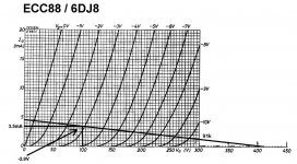
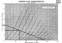
Loadlines for the 6DJ8 (first stage) and 6GU7 (second stage)
The real life 6DJ8 doesn't agree completely with its spec sheet.
Incidentally, this turned out to be a mere tweak of a circuit JC Morrison published in The Tube Audio Primer back in the early '90s. That, in turn, was nearly identical to a circuit by Arthur Loesch published in Sound Practices, in the "Few Stones Left Unturned" article. It still sounds really good.
Attachments
Last edited:
OK, so I think I learned something...
I think I really like the sound of the last round of changes.
The amp measured very well, with good square waves, high frequency response -3dB at 170kHz (with loop feedback), -3dB @ 32kHz open loop. Good square waves, well damped, etc. Low frequency response -1dB @ 11Hz (closed loop).
I was happy, until I got it home and listened to it a while. I didn't like the character of the sound. It seemed overly "dry" and maybe a little "harsh" in the upper mids and highs. But why?
I decided to investigate the sound of the first stage. I had it with large plate resistors for a flat loadline. Low current, though, only 3.5mA per triode in either a 6DJ8 or 6CG7. I figured I didn't need any more gain than a 6CG7 would deliver, so let's optimize it for that tube, with 7 or 8mA per triode. I had to squeeze a couple of LM317's in for CCS's. (I'm sorry, I just can't fit a little board in there for cascoded DN2540's.)
While I was at it, I reconfigured the 6GU7 driver section, reducing the plate resistors from 22k down to 15k, so the tubes would have more voltage across them. Maybe the loss of linearity would be compensated for by increased headroom. Worth a try.
I fired it up for the first time this evening. It sounds way better. Really good. I'm very happy right now. Lee Morgan's trumpet is like it's in the room. You can easily hear how much they've squashed the latest Blue Note reissues with dynamics compression. Like the radio, but on a CD. Yuck. But it's mastering studio clear now, and much more fun to listen to.
Let's see how I feel about it after I get a look at it on the test bench, and a week of listening to it.
Schematic below.
--
Attachments

Last edited:
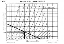
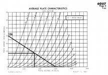
The loadlines for the 6CG7 (input LTP-phase splitter) and the 6GU7 (push-pull driver).
They're certainly steeper than the ones I used before, yet they sound better. Higher current operation in the first stage sounds better? Maybe I like a bit more distortion from the second stage? I dunno...
--
They're certainly steeper than the ones I used before, yet they sound better. Higher current operation in the first stage sounds better? Maybe I like a bit more distortion from the second stage? I dunno...
--
Attachments
After goofing around with the amp for a couple of weeks...
When I had the first 12AT7 version (82k plate resistors, 3mA per triode) of the amp on the scope, it had 10dB of gNFB and showed a little spike of overshoot on square waves. Well-damped and still square at 10kHz, though. The amp at this point was -3dB at 170kHz. I figure that's pretty good for an amp using Dyna OPTs.
Open-loop, the amp is -3dB at about 34kHz.
Then I brought it home, changed the first tube to 6CG7 with 7.5mA thru each triode and 32k plate resistors, decided I didn't like the sound as much as with the 12AT7. I put the 12AT7 back in the first stage, but this time with the 7.5mA and 32k plate load resistors. I like this, even though that is only about a 2:1 ratio between plate load and rp. What the heck, it sounds good this way.
The 6CG7 1st stage LTP never sounded full-bodied enough for my taste, even with a good 4:1 plate load to rp ratio, and after getting the plate current up to 7.5mA. But the 12AT7 with that much current floats my boat.
I reduced the gNFB to an estimated 5dB. The bass is a bit loose, but the mids and highs are nice.
I like it enough this way that I have no plans to change it. I will try to get it to my friend's bench for testing.
--
PS - I'm connecting my nominal 8-ohm Snell Type J/III's to the 4 ohm taps on the OPTs. That should be doubling the apparent primary load, hopefully from 4k3 to 8k6:VC. If that's correct, then that is a very good load for triode-wired 6L6GC's.
Attachments
Last edited:
No, I couldn't leave well enough alone.
Well, I'm enjoying this amp. I changed a few things, basically dialed in the operating points to what I think are better ones.
- Changed the CCS in the 12AT7 tail to 11mA
- Changed the 12AT7 plate resistors to 47k
12AT7 op points
B+ = 400V
Va = 150V
Vg = -1V
Ia = 5.5mA
- Changed 6GU7 tail resistor to 9k
- Changed the 6GU7 plate resistors to 13k
6GU7 op points
B+ = 440V (295V plates to cathodes)
Va = 175V
Vg = -7V
Ia = 9mA
I tried increasing the bias through the 6GU7 by decreasing the value of the cathode resistor, but it made for severely imbalanced voltages side-to-side. With 12mA per 6GU7 triode (using a 6.2k cathode resistor) one 6GU7 triode had only -1V bias while the other had -10V bias. Obviously one side was hogging all the current. This is dependent on the 6GU7 I was using, but the one that exhibited the problem tests good in my tester. So I gave in and set the circuit so it would balance well enough with whichever tested/good 6GU7 I put in there.
--
- Status
- This old topic is closed. If you want to reopen this topic, contact a moderator using the "Report Post" button.
- Home
- Amplifiers
- Tubes / Valves
- Dyna ST70 to Dual-differential EL34 triode amp project