I've been playing with this circuit now for a few days. It can sound very good but there is a noise issue I'm not sure how to approach. When the "right side" SVCS board is set to anything above 108 VDC there is a white noise (pfffffff) audible on the speaker. (The noise off-on knee is sharp, over something like a volt or two) If the other SVCS is taken up above about 120 that noise increases by something like a third. If I take the right hand plate on its own up to about 180VDC the noise then stops.
Thinking there might be some kind of current source interaction between the SVCS and the LM317 I have tried bypassing the SVCS loads with 180K and also 100K resistors. I've also tried bypassing the driver tubes with a 180K resistor from plate to ground. I think the noise is lowered a little in each case but by hardly enough to justify leaving the resistors in.
The amp sounds great with the driver plates below 108V but the operating point can hardly be dictated by the limits of a problem. I believe something is oscillating but where and why I don't know.
I also tried resistors for plate loads. No hiss but the sound isn't nearly as good as with the SVCS. Can anyone offer suggestions?
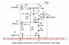
The SVCS board circuits are as in the Schematic posted here but with Q1 = ST P3NK80Z , Q2 = FQU11P06TU , Q3 = MJE5731A
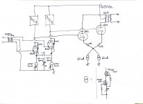
Also not shown on my drawing both 8233's have 100R stoppers on G1
Thinking there might be some kind of current source interaction between the SVCS and the LM317 I have tried bypassing the SVCS loads with 180K and also 100K resistors. I've also tried bypassing the driver tubes with a 180K resistor from plate to ground. I think the noise is lowered a little in each case but by hardly enough to justify leaving the resistors in.
The amp sounds great with the driver plates below 108V but the operating point can hardly be dictated by the limits of a problem. I believe something is oscillating but where and why I don't know.
I also tried resistors for plate loads. No hiss but the sound isn't nearly as good as with the SVCS. Can anyone offer suggestions?
The SVCS board circuits are as in the Schematic posted here but with Q1 = ST P3NK80Z , Q2 = FQU11P06TU , Q3 = MJE5731A
Also not shown on my drawing both 8233's have 100R stoppers on G1
Attachments
I've been playing with this circuit now for a few days. It can sound very good but there is a noise issue I'm not sure how to approach. When the "right side" SVCS board is set to anything above 108 VDC there is a white noise (pfffffff) audible on the speaker. (The noise off-on knee is sharp, over something like a volt or two) If the other SVCS is taken up above about 120 that noise increases by something like a third. If I take the right hand plate on its own up to about 180VDC the noise then stops.
Thinking there might be some kind of current source interaction between the SVCS and the LM317 I have tried bypassing the SVCS loads with 180K and also 100K resistors. I've also tried bypassing the driver tubes with a 180K resistor from plate to ground. I think the noise is lowered a little in each case but by hardly enough to justify leaving the resistors in.
The amp sounds great with the driver plates below 108V but the operating point can hardly be dictated by the limits of a problem. I believe something is oscillating but where and why I don't know.
I also tried resistors for plate loads. No hiss but the sound isn't nearly as good as with the SVCS. Can anyone offer suggestions?
The SVCS board circuits are as in the Schematic posted here but with Q1 = ST P3NK80Z , Q2 = FQU11P06TU , Q3 = MJE5731A
Also not shown on my drawing both 8233's have 100R stoppers on G1
Are you sure that this is nose and not oscillation? Did you measure noise spectrum (FFT)? When you use complex circuits like SVCS, they can oscillate at frequencies up to tens of MHz.
Last edited:
... I believe something is oscillating but where and why I don't know.
Also not shown on my drawing both 8233's have 100R stoppers on G1
So you do think it's oscillating, which seems likely to me also.
The power supply is totally decoupled by R7, C3, and Q1 which set a steady DC voltage to the gyrator.
You do have grid stoppers on the 8233s
So the obvious is covered...
Your triode connection already provides plate resistance, which is why your addition of load resistors only changed the onset of the oscillation.
I'd get a wideband scope on it and see if the oscillation is common mode or differential.
Last edited:
Hi Ian,
First question - If you have CCS-type anode load, why CCS cathode bias? The dc path is confined to each 8233, so if the two CCS unit get different ideas about what the current level should be then there could be a fight. Does the trouble stay away if you switch to resistors in the cathode (or LED(s) if you want all the gain)? I would start with resistors, as lowered gain may be helpful.
If the 8233 is the type I'm thinking of [aka E55L] then you make 50mA/V in triode! That will need some serious precautions against oscillation in any connexion. I doubt that 100R grid stopper is high enough - I would experiment with much higher values. Please check that the anode wiring is as short as can be, and that the SVCS units are reasonably spaced away from the grid-associated parts: coupling of only a few pF between these sections can provide the undesired feedback at VHF.
Sometimes, audible oscillation is actually HF or VHF oscillation, with an audio envelope. Means to check for high frequency behaviour is worth looking into: scope for preference, but a portable radio is useful as a guide.
The circuit has a constant voltage gyrator on top, a resistance in the middle, and a CCS on the bottom. Sound familiar Rod ;-)
But actually the CCS is a tail so only maintains constant total current in the 2 cathodes.
That's why I would suspect a common mode oscillation. Both tubes get involved due to the high impedance tail. More stopper-age may help but maybe you can puzzle out what's really happening.
It most likely is RF oscillation sounding like a sharp hiss.
Last edited:
Wow you guys. I'm overwhelmed. How to put together a cohesive reply ? . . . . .
FIrst two replies are now moot. But to Chris I'll say that on your suggestion I did put 100R grid stoppers on the 2A3 but no effect on the oscillation. On your suggestion of decoupling, I took it to refer to channel to channel PS filter split on the last stage, one for each. As this is only a mono amp that wouldn't apply but your suggestion prompted me to try a separate RC (220R/200uF) stage ahead of each of the SVCS boards. It didn't kill the oscillation but I got the impression it might have raised the Q a little. This was from watching the voltages as I adjusted the driver loads. They seemed to be a little more tightly averse to settling whenever I got close to matching them exactly. A little like magnets with both north poles facing getting the most skittish the closer to perfect alignment you get.
Michael, Thanks for jumping in. I've tried shorting the output stage grids to each other with a cap to see of noise source was input or output stage and the noise stopped. If the oscillation was common mode in the output stage would the cap stop it?
I also appreciate your intent to locate the source. I don't think stoppers improve sound and would rather eliminate the need for them.
Rod, What can I say dude. I still don't know how to use LT Spice and have to build everything that looks interesting enough. It's tedious sometimes but there's nothing for it I'm afraid. I got interested in the driver cathode arrangement after seeing Shoog's post on his own amp with that config on the output stage. It's just struck me as being worth trying. Then, being a big fan of Wavebourn's SVCS circuit it occurred to me that using it would allow me to direct couple the two stages, using the ccs's in the drivers to get them operating in a more or less balanced way and using the SVCS output voltages to balance the output tubes. That's more or less the idea. Sheldon explained the SVCS circuit to me in a way that made me see how it is a morph of a typical CCS so I can understand your thinking. But I also ran across references to the possibility of using it this way ( - though I confess I found no examples of its actually being tried.) I will try upping the stoppers and will tidy up the plate wiring, though it IS a breadboard and spaghetti is the side dish.
Shoog, It's clearly a neat sounding circuit. Thanks very much for posting on your amp. What do you recommend?
ANyway, I'll try putting a scope on it tonight. I don't have a differential probe that I trust but maybe with two probes and channels I can see what's what.
If anyone has setup suggestions I'm all ears.
Thanks
I used the simple cascode MJE340 double transistor CCS which was popularized on this board in a similar situation. I use LM317's on output stages, but at that point the requirements aren't quite so exacting as in the front end - where imbalance will propagate all the way to the output.
I had real issues with the output stage on my amps using CCs and direct coupling. Gary Pimm had the same issues with his Tabor amp (which my amp designs are based upon). Basically the full voltage momentarily developed across the CCS at power up - which in your case would be 420V, or possibly more due to inductive spiking across the OT. A simple LM317 will toast instantly in this situation. I eventually overcame the problem on my latest amp by using a LM317HV equivalent which is good to 250V and also protected it with a 100V zener. The B+ on this amp is only 120V so all has been fine so far.
I also built a Tabor clone using 807's and went through a year of hell trying to find CCS which would withstand power up transients, eventually I ended up using some of the IXY 900V chips which have been fine ever since.
The great and amazing thing is that this arrangement of input-output constant-current operated direct coupled stages has been in operation for over a year at 15hrs a day with no issues and no need for any form of adjustment. Eventually I expect the voltage across the CCS to drop below a functional level as the valves age and then the amp will start to oscillate - but so far so good.
My gut feeling as to your problem is that above about 10Khz the LM317's are dropping in impedance to far below the gyrators impedance and there is a conflict at the point of transition. If that is the case then making the cathode CCS much stiffer will probably sort the problem out.
Shoog
Last edited:
OK thanks. Once the circuit is understood and stable I'll get around to putting a resistor under the output stage CCS to make an 18V rail. I'm told the 317 sounds much better with more voltage across it and then once the rail is there I can also try the different ccs circuits from Walt Jung's article. I'll try the 350 cascode then too. Thanks
I was referring to the input stage.
However I do have a slight concern about the output stage. The capacitor cross coupled output stage in my designs ensures that the current through the output transformer is perfectly balanced, but also that the two stages automatically adjust to create this. Without this arrangement - and employing direct coupling from the input stage, you could develop a sever imbalance in the output stage because the input will have different plate voltages and hence will be creating different biases on the output stage - in your design there is absolutely no way to correct for this. You need the same bias arrangement on both the input and output for this circuit to become universally stable.
I would advocate moving the output stage CCS to the input stage (reducing current setting) and moving the input stage CCS to the output - swapping out the low voltage LM317's for HV versions , with zener protection for start up protection.
Shoog
Last edited:
First question - If you have CCS-type anode load, why CCS cathode bias? The dc path is confined to each 8233, so if the two CCS unit get different ideas about what the current level should be then there could be a fight.
At the moment I don't have my copy of it laying around here, but Morgan Jones' Valve Amplifiers, 3rd edition, also contains a silly mistake similar to this one: A LTP phase inverter, built around an ECC83, with one CCS in the tail (which is a good idea) and two CCSs, one in each anode circuit
 . I never managed to get this circuitry working fine, but thinking it through eventually led me to the solution.
Another misapprehension found in this book: His assertion that split coupling helps to eliminate, or al least reduce DC magnetism in the OT of a SE output stage.
Best regards!
Try to put resistors in series with each of 3 current sources: to cathode, and to both anodes. It decreases influence of their effective capacitances on the tube. Don't be afraid to put something that causes 1-10 volts drop, transistors will only thank you because they would dissipate less of heat.
Sorry, Wavebourn,
but resistors don't have any influence on the currents through each CCS if the total voltage is big enough. I think Jones' circuitry would work fine if the sum of both anode currents, determined by this CCSs, would exactly match the common cathode current, determined by the cathode CCS. But this would be more than accidentally...
Best regards!
Sorry, Wavebourn,
but resistors don't have any influence on the currents through each CCS if the total voltage is big enough. I think Jones' circuitry would work fine if the sum of both anode currents, determined by this CCSs, would exactly match the common cathode current, determined by the cathode CCS. But this would be more than accidentally...
Best regards!
Don't be sorry Kay, better read carefully the topic title and starting message. Also, reading schematics helps. CCS-es in anodes here are not just ordinary CCS-es. They are CCS-es with servo by voltage, so called SVCS, Stable Voltage Current Source. And they supply not incedental current, but the current needed in order to set certain voltages on anodes in respect to the ground. I.e. on DC it is a constant voltage source, on AC it is a constant current source.
Resistors do have influence, because current sources are not ideal. They have own high enough dynamic resistance that is finite. Also, this resistance is complex, and have a capacitive part. So, adding a resistor in series we increase resistive part of impedance on high frequencies that is in series with it's capacitive part.
Please don't hestitate to argue, we can help you to understand deeper what you are arguing about.
Sincerely,
Anatoliy
I was referring to the input stage.
However I do have a slight concern about the output stage. The capacitor cross coupled output stage in my designs ensures that the current through the output transformer is perfectly balanced, but also that the two stages automatically adjust to create this. Without this arrangement - and employing direct coupling from the input stage, you could develop a sever imbalance in the output stage because the input will have different plate voltages and hence will be creating different biases on the output stage - in your design there is absolutely no way to correct for this. You need the same bias arrangement on both the input and output for this circuit to become universally stable.
I would advocate moving the output stage CCS to the input stage (reducing current setting) and moving the input stage CCS to the output - swapping out the low voltage LM317's for HV versions , with zener protection for start up protection.
Shoog
You might be right. I don't know yet. But I'm also not sure you understand my intent. THe SVCS is fully adjustable with an onboard pot. With the LM317 setting the current of the individual drivers, the adjustable SVCS can be set to give desired plate voltages and those being directly coupled to the following grids the voltages can be set to balance the output tubes by grid bias.
Yo! Hi Wavebourn! OK I put 120 Ohms on top of output tubes' LTP CCS and 220R on output of each SVCS to plate. Noise is a little "grainier" (might that indicate a shift downward in frequency?). white noise sound is also a little louder.
Onset of oscillation/noise is still at ~110V on the driver plate.
It's dinner time. I'll try to squeeze in a little soldering and scoping later tonight.
Thanks!!!
Onset of oscillation/noise is still at ~110V on the driver plate.
It's dinner time. I'll try to squeeze in a little soldering and scoping later tonight.
Thanks!!!
I eventually overcame the problem on my latest amp by using a LM317HV equivalent which is good to 250V
Shoog
Can you share the part number? I didn't know there was an LM317 equivalent that goes that high. Thanks.
Can you share the part number? I didn't know there was an LM317 equivalent that goes that high. Thanks.
The part I used was the TL783CK which is good to 125V not 250V - my mistake.
Zener protection with a 100v zener will help.
---------
I now see that yours can be adjusted, but placing the cap coupled bias on the output makes it self adjusting which for me is nice.
Shoog
- Status
- This old topic is closed. If you want to reopen this topic, contact a moderator using the "Report Post" button.
- Home
- Amplifiers
- Tubes / Valves
- Differential Amp CCS Tail SVCS Plate - Noise Issues