Well I just know that valve rectifiers do not like large capacitances (the largest I know of is 60uF for GZ34) and those enormous ones would look like prolonged short circuits. As an example the famous U19 HV rectifier had a limit of just 4uF. And as I say there is no need for those huge capacitors. You can I am sure quite easily calculate what your output ripple voltage will be; as I recall calculating ripple current is less easy. By the way be sure to fit snubbers to your choke input supplies; something like 0.22uF at 2kV I guess.
I presume the current capacity of the 10H chokes is sufficient for the job? remember that in a choke input supply the choke has to have a rating much greater than the load current and the higher the voltage the higher the additional requirement.
P.
I presume the current capacity of the 10H chokes is sufficient for the job? remember that in a choke input supply the choke has to have a rating much greater than the load current and the higher the voltage the higher the additional requirement.
P.
Last edited:
yep...excessive capacitance will stress the tube but the choke should have allowed for such large value of capacitance.
the choke is 10H rated at 1A continous and tested at 2500v. I suspect it will do the job nicely (predicted screen current is max 500mA at full load).
This is just screen voltage so max 650v.
the choke is 10H rated at 1A continous and tested at 2500v. I suspect it will do the job nicely (predicted screen current is max 500mA at full load).
This is just screen voltage so max 650v.
as I said i had them handy (scavenged for a dime)....were new...and looked nice (very technical reason) also all simulations said they would have worked...
Maybe a load is required to see some voltage?
yes I hope either tubelab.com or pmillet or any other expert will join the conversation. This is stretching tube psu design so it might just help people avoid stupid mistakes (like the ones I made).
the other boards, on the other hand, work perfectly")
Maybe a load is required to see some voltage?
yes I hope either tubelab.com or pmillet or any other expert will join the conversation. This is stretching tube psu design so it might just help people avoid stupid mistakes (like the ones I made).
the other boards, on the other hand, work perfectly
assembly of top plate completed. Remaining slot is for an additional gain stage.
Looking good!
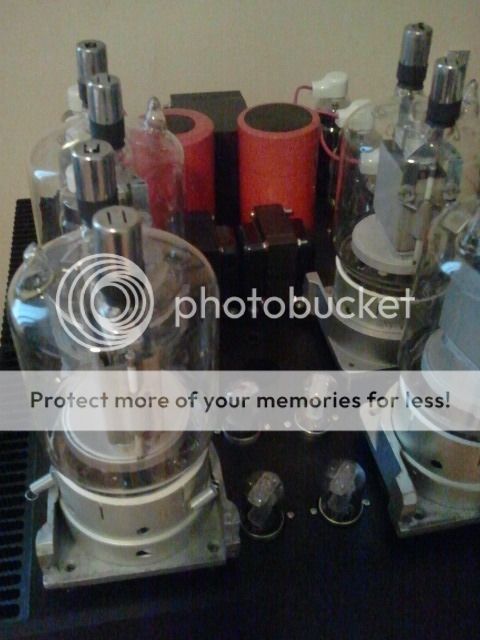
You asked earlier, and I don't know if it was answered. But yes, I'd say those large electrolytic caps will get way too much radiated heat. I would put a reflective shield between the caps and tubes, and probably a small fan to clear the air inside the shield. Maybe a u-shaped shield. Or perhaps a cylinder around each cap with a cm or so of clearance (again add something to actively move cool air around the cap - small fan should do).
The tubes themselves can tolerate the radiated heat better than the caps, as long as you de-rate them by 25% or so and move the air.
Sheldon
Last edited:
Hi Sheldon, thanks for posting! The truth is maybe the caps are useless anyways so just for aestethics I'll leave them on the top panel but somehow filterthe screen voltage within the amp. The temperature is actually much lower thann expected. With 866A the closest section of the capacitors barely gets warm!
the filaments are unfortunately undervolted by 16% (too much drop in xformer voltage output) but can that account for NOT having a hot surface?
the filaments are unfortunately undervolted by 16% (too much drop in xformer voltage output) but can that account for NOT having a hot surface?
here:
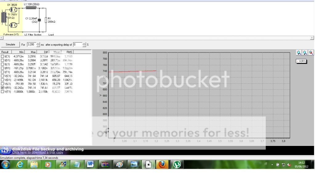
only difference is that I use a filament transformer's CT to extract the rectified sine.
the 200k load are the 2 balancing resistors in series. (2x100k)
Schematic = schematic
PSUD2 simulation =/= schematic.
here:
only difference is that I use a filament transformer's CT to extract the rectified sine.
the 200k load are the 2 balancing resistors in series. (2x100k)
That's a no load condition. What is the current draw for the actual circuit?
The temperature is actually much lower thann expected. With 866A the closest section of the capacitors barely gets warm!
the filaments are unfortunately undervolted by 16% (too much drop in xformer voltage output) but can that account for NOT having a hot surface?
The temperature measured with the amp fully functional and drawing the expected current?
Which filaments undervolted?
Sheldon
1) the temperature is the normal "idling" temperature of the voltage boards. obviously no heat is coming from the gu81m so that is another matter. I merrely stated that fully functional rectifiers do not manage to get the caps warm.
2) unfortunately the filaments on the recttifiers are 2.1v. I need to install a stepup transformer. At 2.1v I risk destroying the filaments by virtue of ion bombardment
3) the load as it is in the amp is 200k. Under heavy load the estimated is 400mA 500mA but that is under extreme use. In any cas despite the very little amount of current draw we should be seeing voltage at the screen leads. 34mV means something is wrong (the value itself grows proportionally to the turn of the variac. So if it is 2mV at 22ish AC volts it grows to 34mV at 110v mains)
4) the currnt drawn I think approximates 0.5A per tube. I have never seen such a glow from 866A. Not even my huge mercury gastrons put out that much light.
Would a busted cap somehow behave like this?
the voltage is 2.5v (heater voltage) but anode voltage is correct so the problem is afte the tubes. Either the choke itself (strange to say the leas since it shows continuity across leads) or the caps.
I will shortly have two caps for screen voltage (600uf max 900v) so I will be able to test the amp more thoroughly.
I got a super bargain today. For 10 euros (all together) I got two of these
60A filter units of a very respectable brand (yes sixty amps).
I know ther are more pressing matters but it still seemed to be a good deal. One for heaters and one for HV.
I will shortly have two caps for screen voltage (600uf max 900v) so I will be able to test the amp more thoroughly.
I got a super bargain today. For 10 euros (all together) I got two of these
An externally hosted image should be here but it was not working when we last tested it.
60A filter units of a very respectable brand (yes sixty amps).
I know ther are more pressing matters but it still seemed to be a good deal. One for heaters and one for HV.
If I were you I'd replace the tube rectifiers with diodes to make sure the rest of the circuit works as intended. Once you get the correct values and proper filtering you can worry about the rectifier quality later.
Those large caps will draw a lot of current at turn on, much more than what the tube rectifier can safely pass.
Those large caps will draw a lot of current at turn on, much more than what the tube rectifier can safely pass.
If I were you I'd replace the tube rectifiers with diodes to make sure the rest of the circuit works as intended. Once you get the correct values and proper filtering you can worry about the rectifier quality later.
Those large caps will draw a lot of current at turn on, much more than what the tube rectifier can safely pass.
Yes I doubt I'd run more than 8uF with the 866s - even after the choke!
P.
- Status
- This old topic is closed. If you want to reopen this topic, contact a moderator using the "Report Post" button.
- Home
- Amplifiers
- Tubes / Valves
- High voltage driver for AB2 operation GU81m tubes