Ok I did some testing:
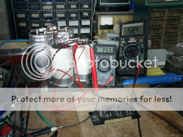
1) I tested the HV transformerwith a diode bridge and a 18,000uf 50v cap. he cap charged and kept the voltage (control test) Hv = fine
2) I used the bridge to energize the circuit in the amp. Yes but voltage output was extremely low compared to input mains and once switched off the variac, the caps did not keep the volage (60v) at all. = caps are bad and were simpy "pumped" a little bit by the bridge's greater current capability.
3) I tried to use the bridge to charge the caps by connecting the output of the bridge directly to the 600v leads (bypassing the choke) = NO GO
4) I paralleled the good cap to the bad caps and obviously the good cap was not charged and showed no residual voltage
My conclusions: the caps are busted. I did try them with a bridge long time ago and seemed okay but maybe poor storage or bad luck caused them to fail. I might have well overlooked the obvious signs of damage.. my bad
my approach:
1. I will remove the choke lead to the caps and do a quick test to see if with a good (smaller) cap I get voltage. If it is so then I will probably add slim type itelcond 450v 1200uf (so 600uf equivalent) caps inside the amp and be done with it.
2. I will test both tube and SS for sine rectifying.
For now by eliminating the bad caps (no screen voltage applieed to the tube anodes) I get a much more silent functioning out of the variac (it hummes increasingly more if I keep the screen voltageon the tubes) and I suppose the temperature of the 2500va core will drop.
I overlooked this major detail. My bad. A lot of things worked as planned. Something had to go wrong.")
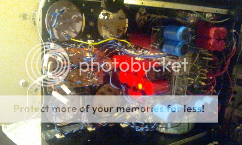
nice glow of the 866a tubes though
1) I tested the HV transformerwith a diode bridge and a 18,000uf 50v cap. he cap charged and kept the voltage (control test) Hv = fine
2) I used the bridge to energize the circuit in the amp. Yes but voltage output was extremely low compared to input mains and once switched off the variac, the caps did not keep the volage (60v) at all. = caps are bad and were simpy "pumped" a little bit by the bridge's greater current capability.
3) I tried to use the bridge to charge the caps by connecting the output of the bridge directly to the 600v leads (bypassing the choke) = NO GO
4) I paralleled the good cap to the bad caps and obviously the good cap was not charged and showed no residual voltage
My conclusions: the caps are busted. I did try them with a bridge long time ago and seemed okay but maybe poor storage or bad luck caused them to fail. I might have well overlooked the obvious signs of damage.. my bad
my approach:
1. I will remove the choke lead to the caps and do a quick test to see if with a good (smaller) cap I get voltage. If it is so then I will probably add slim type itelcond 450v 1200uf (so 600uf equivalent) caps inside the amp and be done with it.
2. I will test both tube and SS for sine rectifying.
For now by eliminating the bad caps (no screen voltage applieed to the tube anodes) I get a much more silent functioning out of the variac (it hummes increasingly more if I keep the screen voltageon the tubes) and I suppose the temperature of the 2500va core will drop.
I overlooked this major detail. My bad. A lot of things worked as planned. Something had to go wrong.
nice glow of the 866a tubes though
thanks for the warning, it is true...there is a risk but I have
a) powercoated the tneire top plate
b) added a adhesive vinyl layer under the capacitors
c) the terminal pass through thick rubber grommets
I think it is more likely the caps are busted. Possibly from before I got them
a) powercoated the tneire top plate
b) added a adhesive vinyl layer under the capacitors
c) the terminal pass through thick rubber grommets
I think it is more likely the caps are busted. Possibly from before I got them
1) the temperature is the normal "idling" temperature of the voltage boards. obviously no heat is coming from the gu81m so that is another matter. I merrely stated that fully functional rectifiers do not manage to get the caps warm.
With only a 200k load, the rectifiers are simply putting out the heat generated by the filament. If that's what you expect during operation, then OK.
2) unfortunately the filaments on the recttifiers are 2.1v. I need to install a stepup transformer. At 2.1v I risk destroying the filaments by virtue of ion bombardment
I don't know about mercury rectifiers, but other tubes can often tolerate that much deviation.
3) the load as it is in the amp is 200k. Under heavy load the estimated is 400mA 500mA but that is under extreme use. In any cas despite the very little amount of current draw we should be seeing voltage at the screen leads. 34mV means something is wrong (the value itself grows proportionally to the turn of the variac. So if it is 2mV at 22ish AC volts it grows to 34mV at 110v mains)
I don't understand the design. Is there a complete schematic and I missed it?
At a 200k load and 1000V you are drawing 5mA. For that load 10uF of capacitance in the supply should be fine. And you say the load goes to 500mA max. Even there, 1mF is plenty. This is for the screen supply I presume?
4) the currnt drawn I think approximates 0.5A per tube. I have never seen such a glow from 866A. Not even my huge mercury gastrons put out that much light.
Would a busted cap somehow behave like this?
Well, a 200k load certainly wouldn't allow 0.5mA of current. So if that really is the load, the current has to be flowing parallel to the load. A bad cap could be a path. But the current has to go through the choke. At 58 Ohms, you'd expect to see about 30V across the choke. Do you?
Sheldon
Last edited:
a) the load the rectifiers will see is limited. No more than 50mA between +300v and +500v lines. Screen voltage for the gu81m on the other hand is load dependant so according to the chosen load line we could see a maximum of 500mA @ 600v. at full load. That would mean each tube conducts 250mA maximum assuming almost identical characteristics. In tube rectifiers I have a known voltage drop to ionize the medium (gas or mercury vapor) but really how does that translate to radiated heat?
b) the schematic for the driver is posted in the first pages. The gu81m are fed via a 1500v b+ and 600v screen voltage.
c) 866A datasheet states that voltage must not collapse under 2.38v under load. failure to comply will result in shortened life span.
d) The minimum load is 200k as that is the value the balancing resistors (2x 100k) so we know that a minimum of 3mA is always drawn een before connecting the gu81m. Idling the gu81m will pull much more from the screen line. the gu81m ar not yet connected so right now we are looking at a simple unloaded poer supply section.
In the nex few days I will open the part of the amplifier where the choke is located and cut the lead connecting the choke to the caps. I will then use the good cap to check for voltage. If I get a green light then we know something is wrong with he caps and I can replace them with something new and guaranteed.
a) the load the rectifiers will see is limited. No more than 50mA between +300v and +500v lines. Screen voltage for the gu81m on the other hand is load dependant so according to the chosen load line we could see a maximum of 500mA @ 600v. at full load. That would mean each tube conducts 250mA maximum assuming almost identical characteristics. In tube rectifiers I have a known voltage drop to ionize the medium (gas or mercury vapor) but really how does that translate to radiated heat?
b) the schematic for the driver is posted in the first pages. The gu81m are fed via a 1500v b+ and 600v screen voltage.
c) 866A datasheet states that voltage must not collapse under 2.38v under load. failure to comply will result in shortened life span.
d) The minimum load is 200k as that is the value the balancing resistors (2x 100k) so we know that a minimum of 3mA is always drawn een before connecting the gu81m. Idling the gu81m will pull much more from the screen line. the gu81m ar not yet connected so right now we are looking at a simple unloaded poer supply section.
In the nex few days I will open the part of the amplifier where the choke is located and cut the lead connecting the choke to the caps. I will then use the good cap to check for voltage. If I get a green light then we know something is wrong with he caps and I can replace them with something new and guaranteed.
Just adding twopence-worth here.
When I built a choke input supply for my p-p 813 amplifier, I first tested the supply by simply connecting four 50-watt resistors in series to an appropriate value to simulate my anticipated current draw; unloaded the voltage was about 1.7kV; under load it was 1.1kV.
Now the point of this is not to demonstrate a simple fact except to say that a simple test is often the way forward.
Once again I must insist that you forget about these enormous capacitors (yes, 600uF is enormous). Just go traditional; use 8uF after the choke, connect a suitable high-powered resistor across the output and then test.
Paul
I have a known voltage drop to ionize the medium (gas or mercury vapor) but really how does that translate to radiated heat?
Volts times current. At 100mA average it would be 1.5 watts, given a voltage drop of 15V. Not much to worry about as regards radiated heat. Obviously more of an issue with the output tubes.
Sheldon
Just adding twopence-worth here.
When I built a choke input supply for my p-p 813 amplifier, I first tested the supply by simply connecting four 50-watt resistors in series to an appropriate value to simulate my anticipated current draw; unloaded the voltage was about 1.7kV; under load it was 1.1kV.
Now the point of this is not to demonstrate a simple fact except to say that a simple test is often the way forward.
Once again I must insist that you forget about these enormous capacitors (yes, 600uF is enormous). Just go traditional; use 8uF after the choke, connect a suitable high-powered resistor across the output and then test.
Paul
Hey I'll get all the help I can get!
the only flaw is that the 300v board (choke input tube rectified voltage) has 700uf worth of capacitors and the 500v has 360uf worth. Both display voltage!
I did test all the rectifiers serparately (some pictures are in the thread) so assuming the caps were good it should have worked. I believe the caps to be busted. There is no short to ground as the top panel is well insulated from the contact terminals. Maybe the electrolyte dried up and somehow altered the internal structure of the cap....I wouldn't know.
What I do know is that I will have to bypass the caps...I will experiment as planned to rule out other variables and then use the 600uf (or less) to try and get voltage out.
I have ordered industrial 2.4kohm power resistors in order to create a 9.6kohm load for the HV 1,3kv AC secondary. It will provide a good load for testing other voltages.
How old are your capacitors? Have they been laying around unused for a longer time? Because then the isolating layer will degrade, and a long-time unused electrolytic capacitor will draw a huge current at the beginning until its dielectric layer will have rebuilt. Might end up in a dangerous situation, since the condenser is quickly heating up and building pressure, and might burst in the worst case.... So current has to be limited initially by series resistors until the caps will have reached full voltage without heating up a lot - then they are safe for use. If they heat up during this "reformation" process, stop, let them cool down and restart. This effect is especially visible in the high-capacity electrolytics you are using. Maybe that's the reason for the high current and the low voltage you are seeing?
BTW - thanks for referring to one of my amps in your post #113 (page 12, the "diyaudio amp") I am also a big fan of gas-filled rectifiers! Rarely have had any serious problems with! Good success for your monster project, I love it!
best regards
Uli
BTW - thanks for referring to one of my amps in your post #113 (page 12, the "diyaudio amp")
I am also a big fan of gas-filled rectifiers! Rarely have had any serious problems with! Good success for your monster project, I love it!best regards
Uli
here is a nice link to reforming caps: Reforming Electrolytic Capacitors
or this: http://www.angelfire.com/electronic/funwithtubes/Restore_cap.html
or this: http://www.angelfire.com/electronic/funwithtubes/Restore_cap.html
Great Tony. Thanks!
I found this sentence:
The circuit shown in the sketch above works reasonably well. Apply the rated voltage through a 5W resistor. Anything from 20K-50K will do, as this is far from a precision process. The meter is used to measure the voltage drop across the resistor; when no current is flowing, there will be no drop. Obviously, when there is a large voltage drop (more than 20% of the applied voltage), there must be a significant current flow through the capacitor. The nature of a proper capacitor is to impede DC current flow, so when there is such flow, something must be wrong.
which would seem to describe what we are seeing.
Can I use my existing screen ciruitry to reform the caps?
I can use a simple 18 0 18 transformer and connect it to he anodes of the tube rectifiers. Then I intermittently charge the caps and measure voltagedrop across the choke.
Might it work?
video-2012-06-08-19-35-26.mp4 video by Alexontherocks_2008 - Photobucket
enjoy
the problem with the screen was that the through bolt on one of the filament transformer made contact with the outer windings. Carelessness on my behalf. Luckily the first thing I do in every project is to ground the chassis in a manner that if power on then there is connection between PWR, safety and main GND
I fixed the problem and reinstated the large caps. However all the voltages are way up. The screen voltage (which is almost unloaded except the 100k balancing resistors) climbs to 850v at startup.
I think I need pull some of the voltages down with larger loads (22k is optimal). Aside from the blue glow it shouldd help in this regard. Should it no I'll have to think of something else.
video-2012-06-08-19-35-26.mp4 video by Alexontherocks_2008 - Photobucket
enjoy
the problem with the screen was that the through bolt on one of the filament transformer made contact with the outer windings. Carelessness on my behalf. Luckily the first thing I do in every project is to ground the chassis in a manner that if power on then there is connection between PWR, safety and main GND
I fixed the problem and reinstated the large caps. However all the voltages are way up. The screen voltage (which is almost unloaded except the 100k balancing resistors) climbs to 850v at startup.
I think I need pull some of the voltages down with larger loads (22k is optimal). Aside from the blue glow it shouldd help in this regard. Should it no I'll have to think of something else.
As I pointed out earlier, you have to load a choke input supply; you will then get 0.9 of the rms voltage rating of the transformer - and of course 1.414 x the rms current rating..
Paul
Choke input power supplies have a "critical inductance" for any value of DC loading, below which it doesn't act as a choke input, but rather a cap input. Another way of saying this is that for any particular value of inductance a minimum of some amount of loading must be applied.
By luck, the values of inductance (in Henries) and load in K Ohms are about equal. So if you have a 5 Henry choke the minimum load is a 5 K Ohm resistor. Otherwise voltage will soar to cap input levels.
All good fortune,
Chris
By luck, the values of inductance (in Henries) and load in K Ohms are about equal. So if you have a 5 Henry choke the minimum load is a 5 K Ohm resistor. Otherwise voltage will soar to cap input levels.
All good fortune,
Chris
- Status
- This old topic is closed. If you want to reopen this topic, contact a moderator using the "Report Post" button.
- Home
- Amplifiers
- Tubes / Valves
- High voltage driver for AB2 operation GU81m tubes