I finally cracked it. Final layout!
one side:
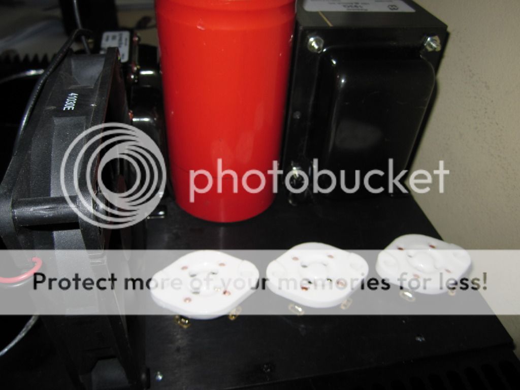
front view..
what you see are the 2x 200mA chokes (anode voltage for driver section) and 1x 500mA for gu81m screen voltage.
2x 4700uf 385v caps for screen voltage.
The three 4 pin sockets are for 3 (per side) 866A type rectifiers.
interesting feature is a fan (8/12cm) which will be hidden behind the gu81m and will provide cooling around the gu81m, between the gu81m and driver tubes and cool the rectifiers all at the same time!
I am very happy with this layout and definitely think this is one of the final (if not the final) layout.
Any observations?
Thanks
one side:
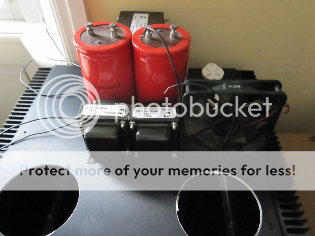
front view..
what you see are the 2x 200mA chokes (anode voltage for driver section) and 1x 500mA for gu81m screen voltage.
2x 4700uf 385v caps for screen voltage.
The three 4 pin sockets are for 3 (per side) 866A type rectifiers.
interesting feature is a fan (8/12cm) which will be hidden behind the gu81m and will provide cooling around the gu81m, between the gu81m and driver tubes and cool the rectifiers all at the same time!
I am very happy with this layout and definitely think this is one of the final (if not the final) layout.
Any observations?
Thanks


Possibly my last posts were unclear. The cold start was still preceded by warmup time (30 minutes). I simply meant the voltage was not ramped but switched on (simulating a system with heavy initial load and no softstart).
The flaking is not due to the current since at 280v the tube should be able to conduct almost 500mA of current.
The flaking is not due to the current since at 280v the tube should be able to conduct almost 500mA of current.


")


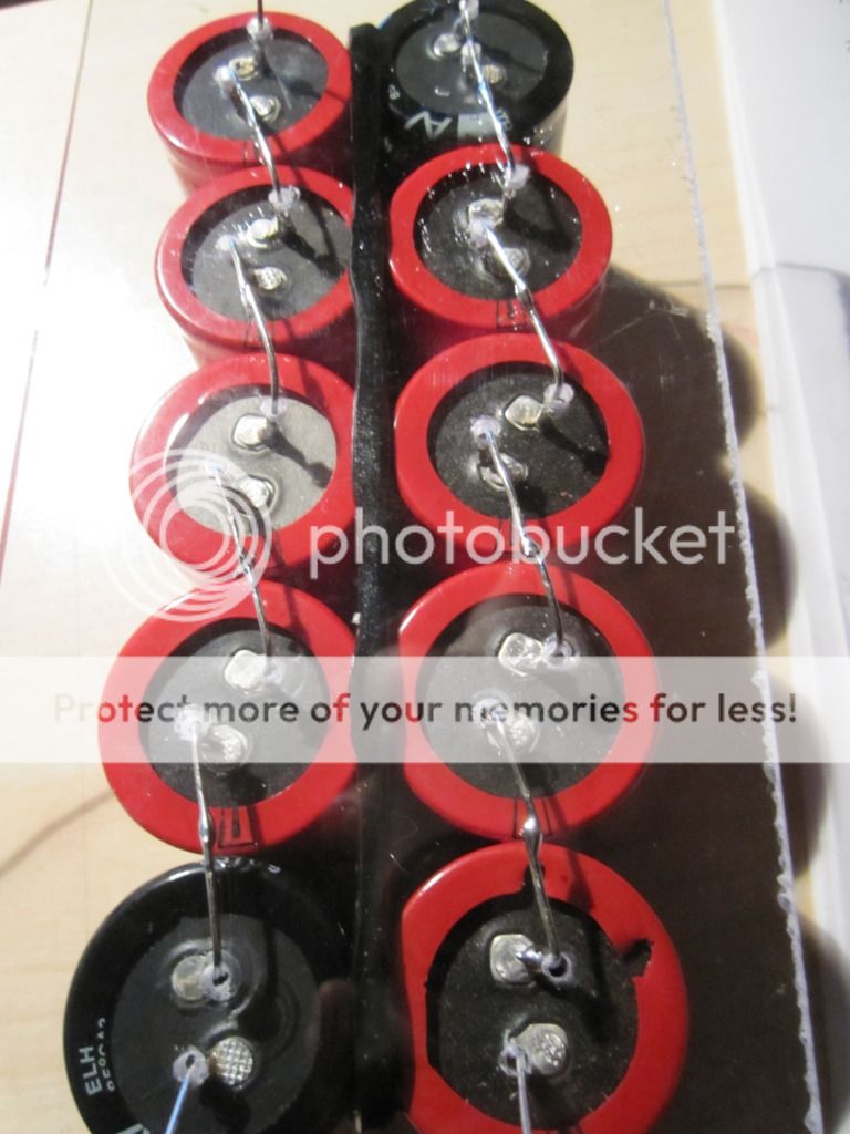
To increase HV efficiency, the transformer will require bridges. with gas rectifiers that can be accomplished either with tube based design or using a hybrid solution. I prepared a board to accomodate the "half bridge" required for hybrid operation. The common bus goes to main PWR ground.
The two relays above are soldered in parallel so that both will close upon power on. The main switch will not power the filament transformers to avoid sparks/damage. It will power a sall supp,ementary transformer which will in turn power on all the transformers and driver stage bias (-12v).
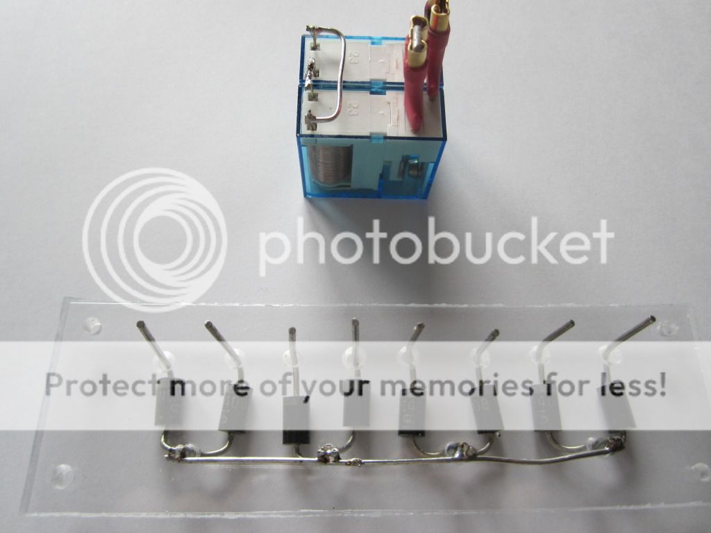
The two relays above are soldered in parallel so that both will close upon power on. The main switch will not power the filament transformers to avoid sparks/damage. It will power a sall supp,ementary transformer which will in turn power on all the transformers and driver stage bias (-12v).
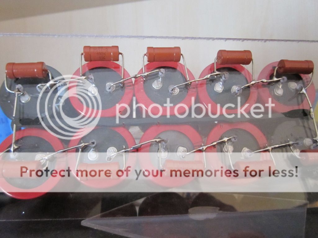
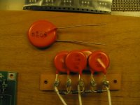
I actually equalised the resistors with 2w 100k resistors just after posting the first photos...
what I don't know exactly is how to balance the diodes. 400k resistors in parallel?
I think capacitors are much better for reverse voltage balancing and snubbing at the same time. 10nF@3KV and the big one is 10nF@6KV
Attachments
- Status
- This old topic is closed. If you want to reopen this topic, contact a moderator using the "Report Post" button.
- Home
- Amplifiers
- Tubes / Valves
- High voltage driver for AB2 operation GU81m tubes