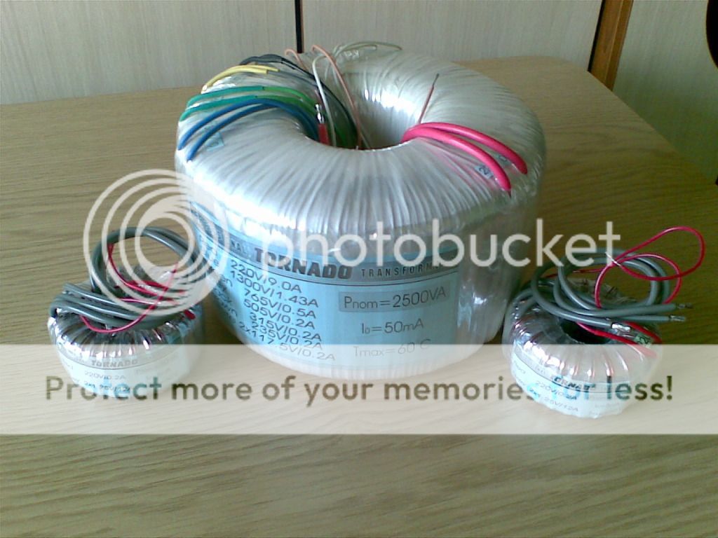
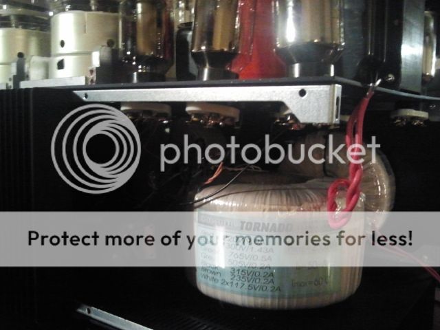
There is obviously a typo: it is not 220v @ 9A but rather 11,36A
Also the lines in Italy are 230v but my mains are more like 225v. So all voltages are bumped by 2.5% and this is quite useful as more filters will be added to avoid "motorboating" and such. Thse will be RC filters so a small drop in resistance is to be taken into account.
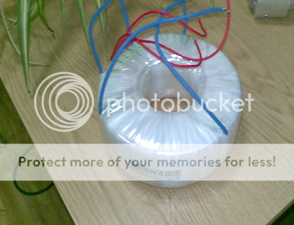
the small transformers will power the 4 866A tubes.
Also the lines in Italy are 230v but my mains are more like 225v. So all voltages are bumped by 2.5% and this is quite useful as more filters will be added to avoid "motorboating" and such. Thse will be RC filters so a small drop in resistance is to be taken into account.
the small transformers will power the 4 866A tubes.
I have a couple of questions for you guys. Hopefully someone will provide some much needed answers: 
1. The 2500va is indeed large with a 1,3kv secondary. I will be fitting it inside the case behind the gu81m sockets with a through hole bolt. Obvioulsy I will avoid creating shorted secondaries but I was thinking: would there be a positive, tangibile improvement if I were to shield the transformer with some sort of "cover"? I could have a copper form made to cover the transformer. would it be worth the cost?
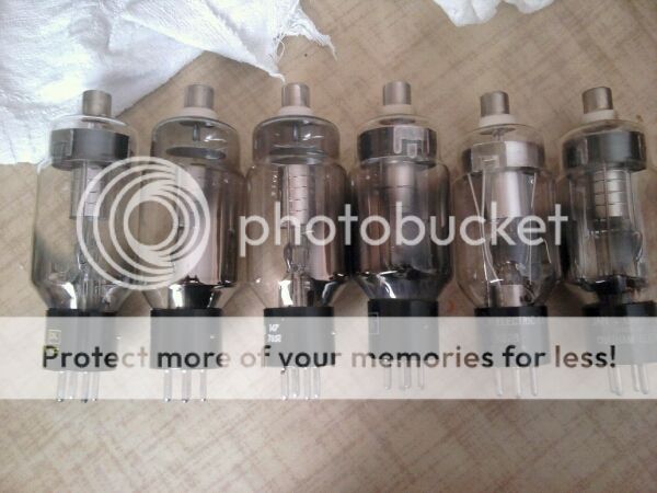
2. I decided not to use the large rectifiers for now. The mounting mechanism I devised is not sturdy enough for my taste and I still haven't found aesthetically pleasing material to make heat resistant grommets...I will use 866A or xenon or other ux base rectifiers.
This takes me to another question. I will end up having a separate transformer for each pair of 866A. The CT will then have its own choke. Provided the windings are separate (ie: 1.25 - 0 - 1.25 + 1.25 -0 - 1.25) could I have all power filaments on the same (adequately sized) core? I suspect so but it would be a pitty to have something of the sort made only to dicover adverse effects.
I hope I managed to explain myself correctly
Thanks
1. The 2500va is indeed large with a 1,3kv secondary. I will be fitting it inside the case behind the gu81m sockets with a through hole bolt. Obvioulsy I will avoid creating shorted secondaries but I was thinking: would there be a positive, tangibile improvement if I were to shield the transformer with some sort of "cover"? I could have a copper form made to cover the transformer. would it be worth the cost?
2. I decided not to use the large rectifiers for now. The mounting mechanism I devised is not sturdy enough for my taste and I still haven't found aesthetically pleasing material to make heat resistant grommets...I will use 866A or xenon or other ux base rectifiers.
This takes me to another question. I will end up having a separate transformer for each pair of 866A. The CT will then have its own choke. Provided the windings are separate (ie: 1.25 - 0 - 1.25 + 1.25 -0 - 1.25) could I have all power filaments on the same (adequately sized) core? I suspect so but it would be a pitty to have something of the sort made only to dicover adverse effects.
I hope I managed to explain myself correctly
Thanks
yep...big indeed. 2500va HV core, 650va LV core, 1700va output transformers....a lot of copper. I would however like to reduce waste and increase efficiency, that is why I'd like to have all gas rectifier power filaments (and center taps) on a single core. As much as this will not benefit the current build it will definitely be handy for the next one (GM100 push pull maybe?)
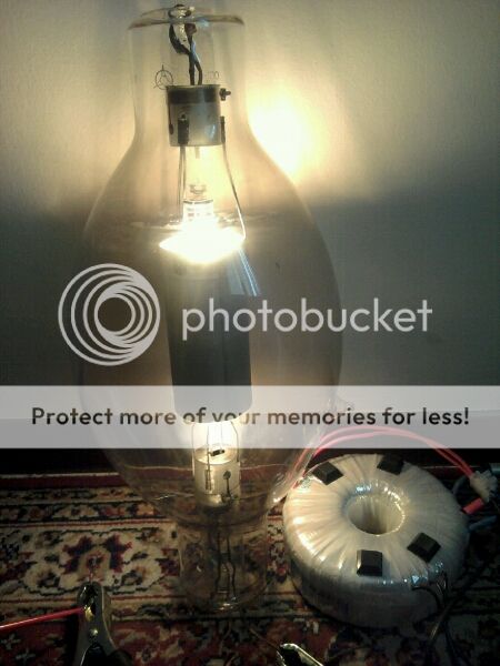


XENON glow 400mA 50v
An externally hosted image should be here but it was not working when we last tested it.
An externally hosted image should be here but it was not working when we last tested it.
Inviato dal mio GT-I9001 con Tapatalk 2
An externally hosted image should be here but it was not working when we last tested it.
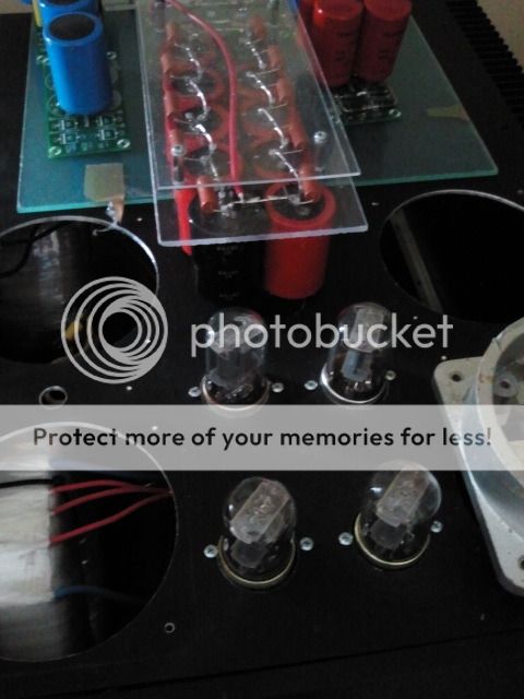
Voltage boards on plexi base. The diodes for the hybrid bridges are in the back.
Inviato dal mio GT-I9001 con Tapatalk 2
all 4000 holes completed and mechanical stuff done.
Turned out very nice if I may say so myself. Simple matter of connecting a few hundred wires.
tubes are obviously tilted since no bolt has yet been placed.
in the middle there are holes for the driver boards and an extra 6sn8 for extra gain if required.
Turned out very nice if I may say so myself. Simple matter of connecting a few hundred wires.
tubes are obviously tilted since no bolt has yet been placed.
in the middle there are holes for the driver boards and an extra 6sn8 for extra gain if required.
So that temperature may become an issue? unfortunately a larger case would have meant an excessive cost and technical issues regarding power connection if i had gone down the three block road ( mono psu dual ampli).
there are fans blowing air through the chassis up to the tubes abd ventilation holes have been drilled to allow some airflow between tubes.
what would be safe operating temperatures for the various tubes? (i mean actual operating values not just datasheet temperatures)
Inviato dal mio GT-I9001 con Tapatalk 2
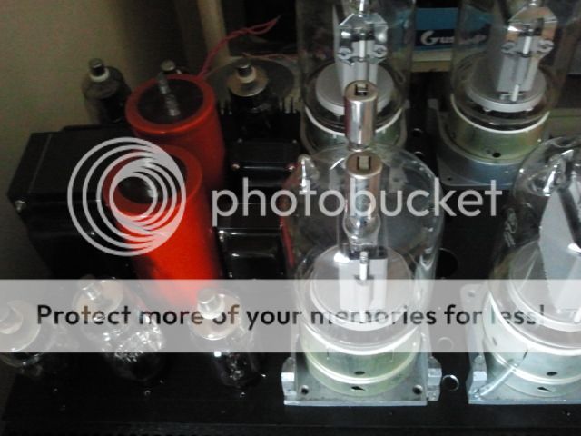
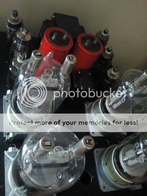
Tony is correct: those big valves are far too close together - just imagine the radiated heat - your fans will help but will do little for the radiated heat.
I ran a pair of 813s in a push-pull amplifier. 813 requires 10v at 5A to light it up plus I was dissipating about 85W on each anode; They got hot indeed. They were spaced about two valves' thicknesses apart. I think you can see what I mean...
I ran a pair of 813s in a push-pull amplifier. 813 requires 10v at 5A to light it up plus I was dissipating about 85W on each anode; They got hot indeed. They were spaced about two valves' thicknesses apart. I think you can see what I mean...
- Status
- This old topic is closed. If you want to reopen this topic, contact a moderator using the "Report Post" button.
- Home
- Amplifiers
- Tubes / Valves
- High voltage driver for AB2 operation GU81m tubes