^that's a 3phase amplifier with 6 rectifiers.....out of reach of most diy'ers that includes me....
@7N7 I have experimented with xenon and MV rectifiers (even large 80kw units), for some light show you can check my prrevious posts. The large rectifiers showed a very very fascinating blue glow.
^that's a 3phase amplifier with 6 rectifiers.....out of reach of most diy'ers that includes me....
Why?
the datasheet is quite clear as for the connections required for 3 phase operation
http://www.r-type.org/pdfs/866a.pdf
Full wave requires 6 tubes of course. The hardest part is having an adequate 2.5v CT transformer and an adequate choke. Both can be manufactured. I have a spare 50A 5v CT on the shelf right now. Could easily power several mercury rectifiers.
I can recall seeing as a small boy (a very long time ago) an enormous industrial mercury rectifier - looked like an illuminated giant squid.
As for the safety aspects, well I think that if they could design and make that contraption, I am quite sure they they would understand all about bleeding down capacitors, though I should imagine they would quickly bleed down anyway with the colossal residual heat in the output valves.
As for the safety aspects, well I think that if they could design and make that contraption, I am quite sure they they would understand all about bleeding down capacitors, though I should imagine they would quickly bleed down anyway with the colossal residual heat in the output valves.
I agree with Tony though, three-phase? probably very costly - and even riskier than usual.
Now what would be nice, would be a 230V supply at say 400Hz; small transformers, easy smoothing.. After all it was used in aircraft - maybe still is; does anyone know?
Now what would be nice, would be a 230V supply at say 400Hz; small transformers, easy smoothing.. After all it was used in aircraft - maybe still is; does anyone know?
you are right...just saying that it looks more like an industrial unit rather than a child-safe household appliance. 🙂
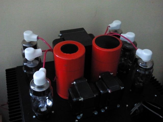
two of these would have rectified my screen voltage if onyl I managed to build a safe enough structure. Was never too happy about my attempts so I chose simple 866A

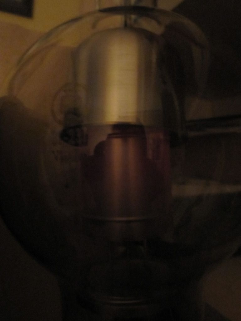
recovering tube after a stressful test:
I will use them for a second project.. 😀
two of these would have rectified my screen voltage if onyl I managed to build a safe enough structure. Was never too happy about my attempts so I chose simple 866A
recovering tube after a stressful test:
I will use them for a second project.. 😀
Last edited:
Alex,
3phase is not available in households at least in Manila, only industrial consumers get to avail of this type of service....
but 3phase rectification brings lots of benefits in terms of psu ripple and regulation...
at least now you have an idea of how not to do the amp.....
3phase is not available in households at least in Manila, only industrial consumers get to avail of this type of service....
but 3phase rectification brings lots of benefits in terms of psu ripple and regulation...
at least now you have an idea of how not to do the amp.....
In Italy one can get 3 phase in houses...depends on main lines ecc but it can be done. People with small garage workshops do it.
In Italy one can get 3 phase in houses...depends on main lines ecc but it can be done. People with small garage workshops do it.
I lived in rural France where the building, formerly part of a farm was provided with three-phase which in fact was not really used - I think two of the phases were used for separate buildings, I understand that it was expensive though.
I have no idea if three-phase is easily available for domestic consumers here in England.
An externally hosted image should be here but it was not working when we last tested it.
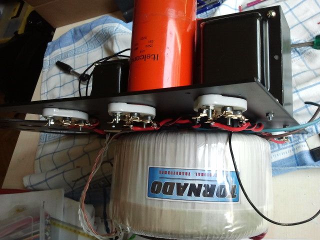
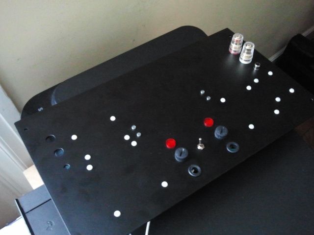
Gu81m sideways. You see the problem with the sockets.
Inviato dal mio GT-I9001 con Tapatalk 2
I chose to follow your advice and have turned the 4 anode plates sideways. It means sacrificing ease in replacing tubes but i think it is well worth it
Inviato dal mio GT-I9001 con Tapatalk 2
Inviato dal mio GT-I9001 con Tapatalk 2
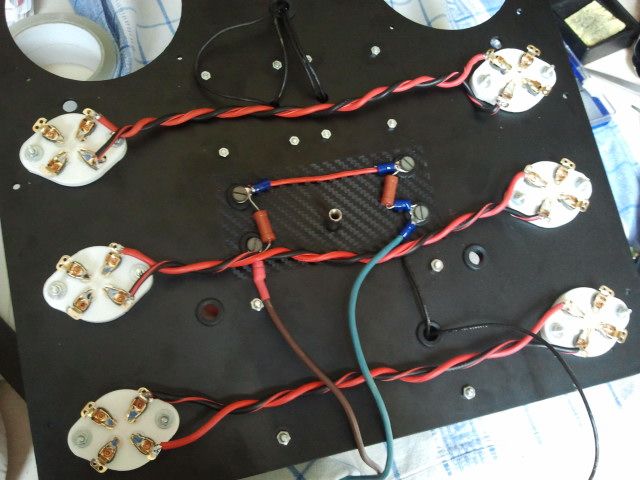
High voltage octopus!
all holes are fitted with grommets and all cables are tested @ 20kv max. Plenty of safety!
all holes are fitted with grommets and all cables are tested @ 20kv max. Plenty of safety!
Love this totally insane project (i'm scared enough by 500V) and keep following it. Please keep posting!
Thanks! a little encouragement is always appreciated.
I am scared of high voltages, but I believe that 1600v can be "tamed" so to speak. Every cable is insulated for at least 3 times the rated voltage, every connection is teflon isolated and covered with heatshrink tubing, all holes are grommeted and the top/back plate themselves are powdercoated.
For the heat issue:
1. the output tube sockets have been lifted by 20mm from the chassis. Air can flow all around
2. the anode plates now face sideways in respect to the front of the amp
3. holes have been drilled to allow for some air to flow vertically bwteen the rectifier tubes and the output tubes
4. two 80mm fans can be connected in the back of the amplifier. The flow should cool the capacitors.
In the end heat and voltage should not pose any threat to the user or the amplifier itself. I say "should" because honestly this is the first amp I have seen that has been designed and built with both compactness, power and aestethics in mind. I have some 1kw 4 ohm dummy loads and am willing to test the thing at full power if I can find a suitable mains connection.
I have a 6kw 230v connection in my house but obviously the outlets can handle much less. At maximum power we should be looking at over 5kw of power drawn... 800w of heaters alone!
The amp now is positively fixed on a wheeled cabinet. It can be tilted to the side. It can even be operated sideways since there is enough clearance between the output tubes and cabinet surface but obviously NOT for extended periods of time.
A positive note is that very little went wrong so far. Every component clears the other components as it should and nothing seems to be "off" in relation to my original design. One small issue.....the power transformer (20kg worth of copper at least) is slightly warping the top plate. As I have done in the past I will exploit the chokes' connection bolts to interpose a steel rectangular bar under the top plate. It "should" add a lot of rigidity to the structure and hopefully reduce the warp. We are talking 3mm off the horizontal plane in the most deformed point but I think it is too much. This amplifier must be perfect! 🙂
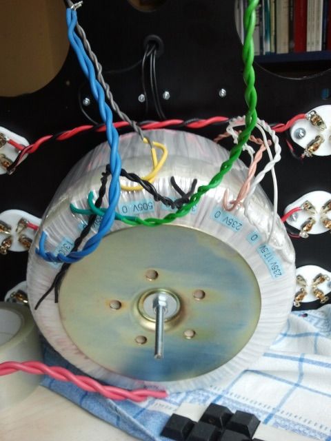
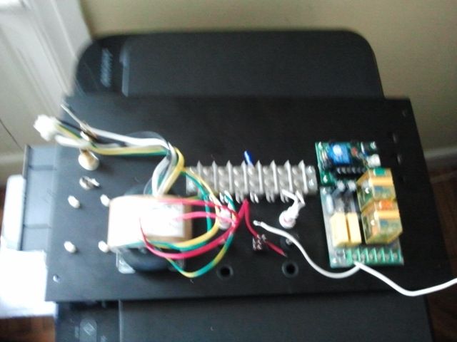
😎small note: there is enough heatercurrent, space and little enough power current in the lines to allow for just any sort of ux4 base rectifier to be used!
I went with the each pair-single transformer package but it would make sense to have a single 2.5v CT transformer with enough tree-wires secondary windings to allow for a more efficient core. 80va cores are much more inefficient than say a nice 250va or 300va core.
can't wait to have all the tubes in warmup mode!
*preparing sunglasses 😎 *
So you are having a certified electrician bring a 3-phase plug directly from your meter, right?
http://www.acharalambous.ltd.cy/images/plugs-3phase2.jpg
http://www.acharalambous.ltd.cy/images/plugs-3phase2.jpg
no...no need for home use.
My home is 230v single phase. 2 cables (one for filament, one for HV) will power the amplifier, possibly from two different outlets.
In any case I will not consume more power than say an inefficient washing machine so no need for 3 phase.
My home is 230v single phase. 2 cables (one for filament, one for HV) will power the amplifier, possibly from two different outlets.
In any case I will not consume more power than say an inefficient washing machine so no need for 3 phase.
Oh I thought you had 3-phase in your house. Misunderstanding. It is kinda common in Greece,
So, I believe the way to do it would be to get a certified electrician,and have him run 2 dedicated lines directly from your in-house box, running in plastic channels, one for filaments and another for HV, with separate appropriate fuses. I have seen tgis kind of installation.
Keep going!!!!
So, I believe the way to do it would be to get a certified electrician,and have him run 2 dedicated lines directly from your in-house box, running in plastic channels, one for filaments and another for HV, with separate appropriate fuses. I have seen tgis kind of installation.
Keep going!!!!
- Status
- Not open for further replies.
- Home
- Amplifiers
- Tubes / Valves
- High voltage driver for AB2 operation GU81m tubes