I've been debating between the Elna Cerafines and the Solens as replacements for the 8 100uf 450v caps... The Solens would be far easier to mount due to the board being designed for axial caps...but if the Cerafines are that much better, I'll make them work...
Opinions on what differences to expect between the two?
They both will cost about $30 each....OUCH!
Would it be worthwhile considering upping the amount of capacitance? The package size of the new capacitors has become smaller with newer technology so I can squeeze more into the same areas if folks think it'd be worth it...
Also, please look at the 220uf 100v units in the power supply. These too can be increased or upgraded if folks think it would be worth it...
Finally, the 100k resistors that parallel the 100uf caps also need to be replaced. Any suggestions on brand for the replacements? They are (I think) 2 or 3 watt units now. They are all very discolored from heat so I figure I should change them while it's apart... I was considering going to 5 watt Mills wirewound units unless others feel it would be a bad idea (if I can get them)...
I am attaching schematics for one channel as well as the power supply...
I'm also open to any other changes/suggestions for improving the circuit... Now is the time as it's completely stripped apart...
Thanks to all for your comments/help!
Attachments
I would like to add one more thing...
If these caps aren't critical to the sound then I would love to save money and use either the Sprague Atoms or perhaps Nichicon's and save a lot of money....
For the 100uf 450v caps, Jadis used CO25 electrolytics manufactured by SIC-SAFCO in France. I can't find any information to tell me if these were just standard electrolytics custom sleeved for Jadis or something special.... If anyone has the specs on them it would be great!
I don't have money to burn...on the other hand I'd like the amp to be the best it can be...
Thanks for your help!
Hi,
Depending on how far you want to push it, no, at first sight these caps don't seem to be critical...not unless you actually heard the difference.
Isn't that always the case?
I'll dig into the schematic of the amp a little more and try to throw in some more suggestions later on.
Cheers,")
If these caps aren't critical to the sound then I would love to save money and use either the Sprague Atoms or perhaps Nichicon's and save a lot of money....
Depending on how far you want to push it, no, at first sight these caps don't seem to be critical...not unless you actually heard the difference.
Isn't that always the case?
I'll dig into the schematic of the amp a little more and try to throw in some more suggestions later on.
Cheers,
Jadis made only one change that I have found so far between my unit and the schematic...
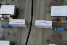
When looking at the fuses on the 6550 output tubes, the fuse bypass cap on the schematic is shown as 1 uf.
On my unit it is .47 uf. Will this make an audible difference? Is it worth changing them?
So far everything else is the same....
One other question:
Would it be possible to add balanced inputs to this unit? Would I simply duplicate the 22pf and 1meg components on the other half of the 12AU7 input tube? (the 22 pf cap that I'm referring to is the one adjacent to the 474 ohm resistor) Then drive each grid with the inverting/non inverting balanced input? Any other components necessary?
Thanks!
Hi,
That should work.
Am I correct in thinking they started with 1µF caps and then later on halved their value?
I have no idea if this would have an audible impact but in theory the bigger value should give a more extended bass response.
Could it be the fuses didn't trip with the larger bypass caps?
Going back to that PSU cap upgrade question, it seems they put 450V caps in series because they didn't want to purchase 500V caps or whatever the reason was.
Since 2 100µF caps in series make for a 50µF cap this opens up possiblities for upgrading to BG caps from their 500V range, say 47µF.
I don't know if you looked at the small pF caps but I'd recommend replacing them with identical silver mica caps.
The 22pF at the source input is probably a ceramic disk type to filter out RFI.
If you think you don't suffer from RFI in your area it may be worthwile to take it out.
Last but not least, the cathode bypass caps on the //ed 12AX7 phase splitter are good candidates for a BG upgrade as well.
Cheers,
Would it be possible to add balanced inputs to this unit? Would I simply duplicate the 22pf and 1meg components on the other half of the 12AU7 input tube? (the 22 pf cap that I'm referring to is the one adjacent to the 474 ohm resistor) Then drive each grid with the inverting/non inverting balanced input? Any other components necessary?
That should work.
On my unit it is .47 uf. Will this make an audible difference? Is it worth changing them?
Am I correct in thinking they started with 1µF caps and then later on halved their value?
I have no idea if this would have an audible impact but in theory the bigger value should give a more extended bass response.
Could it be the fuses didn't trip with the larger bypass caps?
Going back to that PSU cap upgrade question, it seems they put 450V caps in series because they didn't want to purchase 500V caps or whatever the reason was.
Since 2 100µF caps in series make for a 50µF cap this opens up possiblities for upgrading to BG caps from their 500V range, say 47µF.
I don't know if you looked at the small pF caps but I'd recommend replacing them with identical silver mica caps.
The 22pF at the source input is probably a ceramic disk type to filter out RFI.
If you think you don't suffer from RFI in your area it may be worthwile to take it out.
Last but not least, the cathode bypass caps on the //ed 12AX7 phase splitter are good candidates for a BG upgrade as well.
Cheers,
Thanks for the help so far!
"Am I correct in thinking they started with 1µF caps and then later on halved their value?"
I don't know for sure. I searched and found Federico Paoletti's website and found his original drawing. His title on the website is Jadis Defy 7 MK1. I don't know which version of the amp that I have. I do know it is serial number 275... I have no idea of the numbers of these things that are built so I don't know if this is years later in production...
If his schematic is for a MK1 then it would stand to reason that they made the changes in mine a bit later so perhaps your assumption about the fuses not blowing could be accurate. They also added another 22pf cap that bridges both cathodes of the 12AU7 that is not shown on the schematic...
Regarding the large filter caps, do they store more energy when put in series like this? Could that be the reason for two of them? Black Gate only offers a dual 47uf unit in 500v and it's still $95...
Why would the 100k resistors that are in parallel with the filter caps be running so hot? These are the resistors that I mentioned that I was going to change because they are all very discolored from heat... Should I just use a larger wattage or perhaps up the resistance a bit to cool them down?
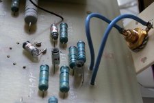
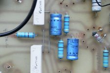
The small input caps are foil types. I'm attaching a few pictures to give you a better idea of what they are...
The ceramic bias circuit and fuse bypass caps - any idea of the brand? Are they decent?
Lastly, when looking at the pics any idea of what brand of resistors they used? I don't know them by looking at them. They appear to be about 2 watt in size...
Thanks for the help!
PS - The writing on the parts and main pcb appears to be factory! There is no screen on the board! Difficult to believe when considering the original price!!!
"Am I correct in thinking they started with 1µF caps and then later on halved their value?"
I don't know for sure. I searched and found Federico Paoletti's website and found his original drawing. His title on the website is Jadis Defy 7 MK1. I don't know which version of the amp that I have. I do know it is serial number 275... I have no idea of the numbers of these things that are built so I don't know if this is years later in production...
If his schematic is for a MK1 then it would stand to reason that they made the changes in mine a bit later so perhaps your assumption about the fuses not blowing could be accurate. They also added another 22pf cap that bridges both cathodes of the 12AU7 that is not shown on the schematic...
Regarding the large filter caps, do they store more energy when put in series like this? Could that be the reason for two of them? Black Gate only offers a dual 47uf unit in 500v and it's still $95...
Why would the 100k resistors that are in parallel with the filter caps be running so hot? These are the resistors that I mentioned that I was going to change because they are all very discolored from heat... Should I just use a larger wattage or perhaps up the resistance a bit to cool them down?
The small input caps are foil types. I'm attaching a few pictures to give you a better idea of what they are...
The ceramic bias circuit and fuse bypass caps - any idea of the brand? Are they decent?
Lastly, when looking at the pics any idea of what brand of resistors they used? I don't know them by looking at them. They appear to be about 2 watt in size...
Thanks for the help!
PS - The writing on the parts and main pcb appears to be factory! There is no screen on the board! Difficult to believe when considering the original price!!!
Attachments
Hi,
No problem, you're as welcome as anyone else...
No, and I don't like caps put in series like this...In theory it's all very well in pracice no two caps are exactly alike which can be problematic in class AB1, or class B amps.
In a class A amp it shouldn't matter all that much but having had major troubles with that kind of setup in my own amps I always steer clear from that.
Current hogging tends to play see saw with the PS, not something I'd consider a plus any audio device.
Energy storage is actually worse then the proper cap for the job, using 600V caps for a, say 500V B+ with a 100µF would actually lower it's available energy.
They look like plastic to me, same things you'd find in the RS Components catalogue.
I prefer ceramic fuseholders of the closed type, less prone to contact deterioration.
These look like bog standard Philips' caps. There's definetily better out there.
I won't even guess, no idea.
Class A tends to do that, keep the same value but up the wattage, non-inductive types preferably.
Yes, Philips or Siemens polystyrenes...make that Philips.
IF at all it is a ceramic disk then, yes it is decent for the job.
No idea about the brandname, I'd clip it out and give it a try...
My guess is it's only there to comply to RFI regulation, the German gov. is pretty severe on that.
They look like Philips metalfilms to me.
Hope this helps,
No problem, you're as welcome as anyone else...
Regarding the large filter caps, do they store more energy when put in series like this? Could that be the reason for two of them?
No, and I don't like caps put in series like this...In theory it's all very well in pracice no two caps are exactly alike which can be problematic in class AB1, or class B amps.
In a class A amp it shouldn't matter all that much but having had major troubles with that kind of setup in my own amps I always steer clear from that.
Current hogging tends to play see saw with the PS, not something I'd consider a plus any audio device.
Energy storage is actually worse then the proper cap for the job, using 600V caps for a, say 500V B+ with a 100µF would actually lower it's available energy.
Ceramic fuse bypass caps
They look like plastic to me, same things you'd find in the RS Components catalogue.
I prefer ceramic fuseholders of the closed type, less prone to contact deterioration.
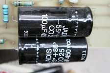
12AX7 Cathode bypass caps
These look like bog standard Philips' caps. There's definetily better out there.
For scale, these are 25mm in diameter and 59mm long...
I won't even guess, no idea.
Why would the 100k resistors that are in parallel with the filter caps be running so hot?
Class A tends to do that, keep the same value but up the wattage, non-inductive types preferably.
The small input caps are foil types.
Yes, Philips or Siemens polystyrenes...make that Philips.
The ceramic bypass caps - any idea of the brand? Are they decent?
IF at all it is a ceramic disk then, yes it is decent for the job.
No idea about the brandname, I'd clip it out and give it a try...
My guess is it's only there to comply to RFI regulation, the German gov. is pretty severe on that.
Lastly, when looking at the pics any idea of what brand of resistors they used?
They look like Philips metalfilms to me.
Hope this helps,
Ok....I appreciate the info...
If I convert the pairs of filter caps to single 47uf units, how should I handle the bypass resistors? Should I just replace the pair with a single 200K 5 watt unit paralleling the cap or should I leave a pair of 100K's in place? Any preference one way or the other?
Regarding the "ceramic" bypass caps... Good eye - you're absolutely correct about them being plastic. I hadn't looked at them very closely... Would it be worth upgrading the fuse holders and at the same time replacing these with something better? Wima perhaps or ? Any recommendations?
Any recommendation on a non-inductive resistor that is rated at 5 watts that goes up as high as either 100k or 200k? It appears that the Mills that I was planning to use don't have values that high....
Now that you know that the input caps are Philips polystyrenes on the 12AU7 cathode, should I change them to silver mica or leave them alone?
Thanks!
Why would the 100k resistors that are in parallel with the filter caps be running so hot? These are the resistors that I mentioned that I was going to change because they are all very discolored from heat... Should I just use a larger wattage or perhaps up the resistance a bit to cool them down?
Hi Apogee
This resistors are for discharging the filter capacitors, in the event that the amp be conected and disconected quickly...in that case the heaters of the valves have no time to put the valve in conduction...and as the capacitors in this case have no load to discharge, they need this bleeding resistors....for not to keep this charge for hours or even days...
regards
Hi,
220K would be the easiest value to find in the 5W resistor range, otherwise, just put 2 440K Rs in //. The exact value isn't critical, these are bleeders after all.
I suspect the only ceramic here would be at the input, the others can be replaced with polystyrenes or better still silver mica.
If you have a capacitance meter, I recommend matching them...it's not mission critical, just me crossing the t's and dotting the i's.
Sure, but where do the Wimas enter the game here? Unless you mean the fuse bypass caps?
I'm no great Wima fan, if you meant the bypass caps BTW.
It's hard to go wrong with a silver mica cap, they're as close to an ideal cap as you can get, consider that a yes.
Cheers,
If I convert the pairs of filter caps to single 47uf units, how should I handle the bypass resistors? Should I just replace the pair with a single 200K 5 watt unit paralleling the cap?
220K would be the easiest value to find in the 5W resistor range, otherwise, just put 2 440K Rs in //. The exact value isn't critical, these are bleeders after all.
Regarding the "ceramic" bypass caps...
I suspect the only ceramic here would be at the input, the others can be replaced with polystyrenes or better still silver mica.
If you have a capacitance meter, I recommend matching them...it's not mission critical, just me crossing the t's and dotting the i's.
Would it be worth upgrading the fuse holders and at the same time replacing these with something better? Wima perhaps or ? Any recommendations?
Sure, but where do the Wimas enter the game here? Unless you mean the fuse bypass caps?
I'm no great Wima fan, if you meant the bypass caps BTW.
Now that you know that the input caps are Philips polystyrenes on the 12AU7 cathode, should I change them to silver mica?
It's hard to go wrong with a silver mica cap, they're as close to an ideal cap as you can get, consider that a yes.
Cheers,
So here's the plan thus far...
Replace the pairs of 100uf 450v filter caps with single 47uf 500v Cerafines (the BG are $95 each - too much for me right now)...
Bypass filter caps with paralleled 440k 3 watt non-inductive resistors.
Replace the small value input polystyrenes with silver mica caps.
Replace the .47uf fuse bypass caps and bias circuit caps with metallized polypropylene or ? Any suggestions here?
Replace the 68uf 63v 12AX7 cathode bypass caps with paralleled 47+22 uf 100v Black Gates.
Add balanced inputs to the chassis and add an additional 22pf and 1 meg resistor to the other half of the 12AU7.
Eliminate the 22pf RFI cap at the input.
Replace the fuse holders with enclosed units. Frank - I've been searching for enclosed ceramic units and can't locate them...Any source that you know of?
Is this everything that's recommended?
Thanks!
The resistors across the power supply filter caps are there to ensure that each cap sees exactly half the rail voltage; in other words, they're a simple voltage divider. Otherwise, the voltage would apportion in proportion to the actual capacitance in each can. Given that electrolytics are pretty sloppy in tolerance, this can lead to a serious imbalance in voltage, possibly leading to the cap failing due to excess voltage.
Whether the resistor quality would have an audible effect depends on your point of view. If you look at a power supply as a place to keep electrons until they're needed, then the answer is probably not. On the other hand, if you look at the caps as a shunt to ground for music reflected in the rails, then suddenly it becomes plausible that they could matter. I calculate the dissipation as being a bit over half a watt each. You could go for 1W, but they'd still be pretty warm to the touch. A good bet would be the metal film Panasonic 3W resistors available from Digikey.
I personally don't have anything against using caps in series that way (as long as the resistors are there), but it does cut the capacitance in half. What I'd do is buy the Solen 47uF 630V film caps and replace each pair of electrolytics with one Solen. The capacitance would be almost exactly equivalent, and you'd have plenty of elbow room on the voltage. Beware, this will change the "sound" of the amp considerably, mostly in the high frequencies. I happen to believe in film cap power supplies whenever it's practical. My tube circuit has a PI filter: two 1000uF 350V electrolytics in series (with resistors) bypassed by two 47uF Solens, then the inductor, then right at 1000 uF of Solens (no electrolytics), bypassed by a couple of uF of MIT styrene caps. Yes, it cost a bloody fortune, but the sound is exquisite.
One thing to watch out for is the size of the Solens. The 47uF is about half the size of your fist. If you can't fit the 47uF in, consider two smaller caps in parallel. If you've got enough space, consider going to a larger cap.
Grey
Hi Grey
you are right...in this particualr case they perform a dual function...bleeder resistors...and making a voltage divider for the elecrolitcs that in this case are in series...
Apogee
The ESR fo capacitors in series is twice the value of each of the capacitors...it will be good you you find a capacitor that have a voltage rating that permit you use only one...and not the two in series...that will be a improvement...
cheers
Hi,
Ah...good question...
From looking at the pics you posted and knowing that in the more expensive models ( even the JA200) they used ICEL caps I'd go for that brand coupling caps, they're excellent.
RS components carries the 1000V and 1500V ones.
BTW, have you noticed that every single 6550 has it's own coupling cap which seems exactly the same as the the fuse decoupling caps?
More work for you but I'd replace these coupling caps with something like a MIT film & foil polyprop as well.
I'm not surprised, this is military stuff.
Anyway those cheap plastic fuseholders can be replaced by the the same but as ceramic ones...
Once again, I think I sourced mine from RS Components UK.
No, but that would require every single resistor...not something I want to recommend unless you're really skilled with a soldering iron.
I even question whether it's worth the effort anyway.
Cheers,
Ah...good question...
From looking at the pics you posted and knowing that in the more expensive models ( even the JA200) they used ICEL caps I'd go for that brand coupling caps, they're excellent.
RS components carries the 1000V and 1500V ones.
BTW, have you noticed that every single 6550 has it's own coupling cap which seems exactly the same as the the fuse decoupling caps?
More work for you but I'd replace these coupling caps with something like a MIT film & foil polyprop as well.
Replace the fuse holders with enclosed units. Frank - I've been searching for enclosed ceramic units and can't locate them...Any source that you know of?
I'm not surprised, this is military stuff.
Anyway those cheap plastic fuseholders can be replaced by the the same but as ceramic ones...
Once again, I think I sourced mine from RS Components UK.
Is this everything that's recommended?
No, but that would require every single resistor...not something I want to recommend unless you're really skilled with a soldering iron.
I even question whether it's worth the effort anyway.
Cheers,
The Apogee Biography...
Hi Frank...
Apogee in this biography state..."Electronics tinkerer and repair guy for years"
Cheers
No, but that would require every single resistor...not something I want to recommend unless you're really skilled with a soldering iron.
Hi Frank...
Apogee in this biography state..."Electronics tinkerer and repair guy for years"
Cheers
Hi,
Actually a triple function....they make for a constant load as seen by the PS as well.
The Defy series being the "Economy" series there's often quite a number of corners cut.
That's just one of them but there's more of those, the more I look the less I want to look.
Cheers,
you are right...in this particualr case they perform a dual function...bleeder resistors...and making a voltage divider for the elecrolitcs that in this case are in series...
Actually a triple function....they make for a constant load as seen by the PS as well.
The ESR fo capacitors in series is twice the value of each of the capacitors...it will be good you you find a capacitor that have a voltage rating that permit you use only one...and not the two in series...that will be a improvement...
The Defy series being the "Economy" series there's often quite a number of corners cut.
That's just one of them but there's more of those, the more I look the less I want to look.
Cheers,
- Status
- This old topic is closed. If you want to reopen this topic, contact a moderator using the "Report Post" button.
- Home
- Amplifiers
- Tubes / Valves
- Jadis Defy 7 Help!