Hi,
True.
I'd only go for the Solen if I couldn't afford the BGs or else go for the Solen Fast Cap series.
Hi Jorge,
LOL....I don't even trust my own eyes, let alone someones else's credentials.
Cheers,")
One thing to watch out for is the size of the Solens. The 47uF is about half the size of your fist. If you can't fit the 47uF in, consider two smaller caps in parallel. If you've got enough space, consider going to a larger cap.
True.
I'd only go for the Solen if I couldn't afford the BGs or else go for the Solen Fast Cap series.
Hi Jorge,
Apogee in this biography state..."Electronics tinkerer and repair guy for years"
LOL....I don't even trust my own eyes, let alone someones else's credentials.
Cheers,
Actually a triple function....they make for a constant load as seen by the PS as well.
That's the theory of Bernard André of YBA...but personaly i can´t see why +- 3 ma can make a constant load for a power suplly that is delivering hundreds of mAmps...
One more hi-fi myth......for me...
Hi,
Really? Why?
It's actually quite simply, the bleeders discharge the caps continuously, hence providing a constant load for the PS and the valves and vice versa.
Mysterious, YBA?
Don't think so, dinosaurian perhaps but effective nonetheless,
One more hi-fi myth......for me...
Really? Why?
It's actually quite simply, the bleeders discharge the caps continuously, hence providing a constant load for the PS and the valves and vice versa.
Mysterious, YBA?
Don't think so, dinosaurian perhaps but effective nonetheless,
Hmmm....
I found the "economy" comment pretty funny!!! Especially considering the $8500 US price tag! (I didn't pay that for it luckily!)
The reason that I asked initially about what changes were recommended is because the more that I looked also the less I liked. I have worked on SS gear for a very long time and to be honest I find the build quality on this amp seriously lacking... That having been said, I don't know tube amps and am trying to be open minded not being familar with tube gear...
Regarding the filter caps, I guess it will be the Solens. Thanks Grey and Frank for the encouragement.... Should be much easier to deal with the mounting... Should I go for the 100uf 630v units while I'm doing it rather than just replacing with 47uf?
I was already planning on changing the coupling caps for the 6550's. I didn't know what to call them and I was referring to them as "the caps in the bias circuit". Regardless, they will also be changed... Should I just use the MIT's to replace all of the .47uf's or should I try to use the ICEL's? I'm confused here....
I was also already planning on reflowing all the solder joints with 4% silver solder so removing the resistors at this point is not a big deal. I had actually already considered replacing them because it's so easy for me to do. Also, it won't cost much to upgrade them... What is recommended for 1% 2 watt replacements?
What about soft recovery diodes in the power supply?
Anything else?
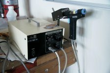
Have no worries regarding my soldering ability. You can be assured that I won't be using solder wick.... All components will be removed using the station in the photo. Ask yourself why someone would bother to buy a dedicated desoldering station unless they had somewhat of an idea of what they were doing...
Thanks!
I found the "economy" comment pretty funny!!! Especially considering the $8500 US price tag! (I didn't pay that for it luckily!)
The reason that I asked initially about what changes were recommended is because the more that I looked also the less I liked. I have worked on SS gear for a very long time and to be honest I find the build quality on this amp seriously lacking... That having been said, I don't know tube amps and am trying to be open minded not being familar with tube gear...
Regarding the filter caps, I guess it will be the Solens. Thanks Grey and Frank for the encouragement.... Should be much easier to deal with the mounting... Should I go for the 100uf 630v units while I'm doing it rather than just replacing with 47uf?
I was already planning on changing the coupling caps for the 6550's. I didn't know what to call them and I was referring to them as "the caps in the bias circuit". Regardless, they will also be changed... Should I just use the MIT's to replace all of the .47uf's or should I try to use the ICEL's? I'm confused here....
I was also already planning on reflowing all the solder joints with 4% silver solder so removing the resistors at this point is not a big deal. I had actually already considered replacing them because it's so easy for me to do. Also, it won't cost much to upgrade them... What is recommended for 1% 2 watt replacements?
What about soft recovery diodes in the power supply?
Anything else?
Have no worries regarding my soldering ability. You can be assured that I won't be using solder wick.... All components will be removed using the station in the photo. Ask yourself why someone would bother to buy a dedicated desoldering station unless they had somewhat of an idea of what they were doing...
Thanks!
Attachments
One last question...
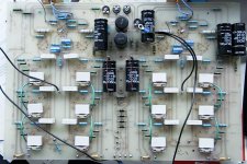
In the center of the board you see two caps standing upright. These are located in the power supply for the bias circuit.
Should I also replace these while I am at it? They are dated 1989... If I can't afford Black Gates here what would be recommended? Elna Cerafines?
Would it be a good idea to up their capacitance while I'm at it? (I've got the space)...
Yes, I meant the Solen Fast Caps.
Put in as much capacitance as you can physically fit (and afford). I've also been known to put caps in a separate box when I ran out of room, but lots of people get nervous about high voltages and don't want to do that. Do whatever suits you, but I wouldn't recommend decreasing the amount of capacitance.
I don't see a 2mA draw (through the voltage dividers) as having that much of a stabilizing effect on the power supply in this circuit, given that the output tubes draw 30mA each. Even one tube swamps the voltage divider, much less a full set. To get much in the way of stabilization, the ratio would have to tip more the other way. That would be pretty wasteful of power in this case. Maybe in a preamp.
Grey
Well it looks like I was a bit over optimistic at this end...
I thought that I had plenty of room to fit a Solen 100uf 630v. Unfortuately, I was looking at the dimensions for the 400v version...
So, if you had to choose between a 100uf 500v Elna Cerafine and a 47uf 630v Solen, which would it be?
Either one will fit and both are about the same money...
Thanks!
I thought that I had plenty of room to fit a Solen 100uf 630v. Unfortuately, I was looking at the dimensions for the 400v version...
So, if you had to choose between a 100uf 500v Elna Cerafine and a 47uf 630v Solen, which would it be?
Either one will fit and both are about the same money...
Thanks!
Hi Everyone,
Please don't give up on me just yet.... I've just about finalized my direction except for the following unanswered questions:
I thought that I had plenty of room to fit a Solen 100uf 630v. Unfortuately, I was looking at the dimensions for the 400v version... So, if you had to choose between a 100uf 500v Elna Cerafine and a 47uf 630v Solen, which would it be? Both are about the same money...
I was already planning on changing the coupling caps for the 6550's. I didn't know what to call them and I was referring to them as "the caps in the bias circuit". Regardless, they will also be changed... Should I just use the MIT's to replace all of the .47uf's in the entire circuit or should I try to use the ICEL's? I'm confused here....
I was also already planning on reflowing all the solder joints with 3.5% eutectic silver solder so removing the resistors at this point is not a big deal. I had actually already considered replacing them because it's so easy for me to do. Also, it won't cost much to upgrade them... What is recommended for 1% 2 watt replacements?
What about soft recovery diodes in the power supply? Is it worth doing on a tube amp?
Again, I really appreciate all the help thus far... I just want this to be the best it can be!
I would like to add one last variable and one last question to the above list of final questions...
What about using the Elna's then bypassing them with film caps? Would this give me the sound of film cap combined with the increased capacitance of the electrolytic? How large should the bypass cap be?
Also, in one of my previous posts I mentioned using two small black gate values to get to a 68uf value. Would it make more sense to just choose a different brand that offers a 68uf value?
I apologize for all of the questions but I'm still learning at this end and don't won't to go off half-cocked....
Thanks!
Hi,
The Jadis would benefit from an increase in PS capicatance, as would most other commercial product.
Whether the Elnas are preferable to the Solen Fast Cap series, I wouldn't know for sure but instinctively I'd prefer the Solens because these are non-polarised filmcaps which should be better than most polarised caps.
I'm no fan of bypassing caps, never have been, so I wouldn't go down that road if I were you.
If $ is no object I'd opt for the MIT RTFX series.
I would leave the resistors in place for the time being but if you want to go all the way replace them with Riken 2W.
Certainly is, incidentally I'll be ordering a number of the new Cree Sic Shottkys for a DA30.
Cheers,
The Jadis would benefit from an increase in PS capicatance, as would most other commercial product.
Whether the Elnas are preferable to the Solen Fast Cap series, I wouldn't know for sure but instinctively I'd prefer the Solens because these are non-polarised filmcaps which should be better than most polarised caps.
I'm no fan of bypassing caps, never have been, so I wouldn't go down that road if I were you.
I was already planning on changing the coupling caps for the 6550's.
If $ is no object I'd opt for the MIT RTFX series.
I would leave the resistors in place for the time being but if you want to go all the way replace them with Riken 2W.
What about soft recovery diodes in the power supply? Is it worth doing on a tube amp?
Certainly is, incidentally I'll be ordering a number of the new Cree Sic Shottkys for a DA30.
Cheers,
Thanks Frank,
Sorry, just thought of one other thing...
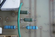
I've attached a photo of what appear to be wire wound resistors. They are green and the manufacturer printed on them is SETA. There are 12 per channel.
Are these decent or should they also need to be changed? What would be the recommended replacement (if necessary)?
Also, regarding the Philips resistors, are they 1 or 2 watt? The body is about 15mm's in length. It's hard for me to tell since I don't have any others to compare them to.... The piece of 16 gauge wire as well as the capacitor should give an idea for scale.
Thx!
Sorry, just thought of one other thing...
I've attached a photo of what appear to be wire wound resistors. They are green and the manufacturer printed on them is SETA. There are 12 per channel.
Are these decent or should they also need to be changed? What would be the recommended replacement (if necessary)?
Also, regarding the Philips resistors, are they 1 or 2 watt? The body is about 15mm's in length. It's hard for me to tell since I don't have any others to compare them to.... The piece of 16 gauge wire as well as the capacitor should give an idea for scale.
Thx!
Attachments
Hi,
These are fine, SETA is Welwyn France.
The colourcoding should give them away but I don't have any tables handy....I think they're one Watt.
Cheers,
Are these decent or should they also need to be changed? What would be the recommended replacement (if necessary)?
These are fine, SETA is Welwyn France.
Also, regarding the Philips resistors, are they 1 or 2 watt?
The colourcoding should give them away but I don't have any tables handy....I think they're one Watt.
Cheers,
Just for reference...
The resistors appear to be Phillips (now BC Components) VR68 1 watt metal films. Jadis used these throughout the unit...
Here's the datasheet on them if anyone else is working on one of these and wonders what they are....
http://www.bccomponents.com/Uploads/Datasheets/vr68.pdf
Thx Frank!
The resistors appear to be Phillips (now BC Components) VR68 1 watt metal films. Jadis used these throughout the unit...
Here's the datasheet on them if anyone else is working on one of these and wonders what they are....
http://www.bccomponents.com/Uploads/Datasheets/vr68.pdf
Thx Frank!
Output Cathode Bypass Fuses
Are they really necessary?
I know in the solid state world that no fuses are good fuses. Is it similar in the tube world?
What about just eliminating all of the fuses and their adjacent .47uf bypass caps? Wouldn't this substantially improve the sonics? At the very least, what about soldering them in?
What exactly are they protecting against? I would guess a runaway tube but does this really happen very often? What will happen without the fuses in circuit if a tube does go south? For the record, I've purchased matched NOS GE's for right now. I just can't do the Tung-Sols yet but given time...
Is it realistic to think that they would actually blow and save something are is the situation similar to speaker fuses on a solid state amp? By the time they blow usually an output has already destroyed itself and about half the time you've lost a speaker as well...
Thanks!
Hi,
'Fraid so. It's either that or risking the tubes...
Cheers,
Are they really necessary?
'Fraid so. It's either that or risking the tubes...
Cheers,
fdegrove said:Hi,
'Fraid so. It's either that or risking the tubes...
Cheers,
Would you mind elaborating a bit? My situation is such that I tend to listen at fairly low volume. My speakers are Apogee Studio Grands and I was planning on using this amp to drive the ribbon tweeters to start with... This is an experiment that I don't know how it will turn out...
The chances of me ever clipping this amp are literally about zero if only hooked up to the tweeter ribbon so will the fuses help in this case?
Are they just there as current limiters for the tubes? If I was willing to trade risking the tubes for better sonics am I putting anything else at risk (transformers, etc?)
Thx!
Hi,
I whish you'd said so right from the start, however I'd not put such a fine amp into such a curtailed service...that's me.
Assuming we want to be more adventurous and keep that amp there I'd jumper the fuses altogether, period.
You know you'd be living a tad more dangerously but the choice is yours.
Obviously I won't take any responaiblity, not for the speakers nor for the amps but that's free advise anuway.
Cheers,
Would you mind elaborating a bit? My situation is such that I tend to listen at fairly low volume. My speakers are Apogee Studio Grands and I was planning on using this amp to drive the ribbon tweeters to start with... This is an experiment that I don't know how it will turn out...
I whish you'd said so right from the start, however I'd not put such a fine amp into such a curtailed service...that's me.
Assuming we want to be more adventurous and keep that amp there I'd jumper the fuses altogether, period.
You know you'd be living a tad more dangerously but the choice is yours.
Obviously I won't take any responaiblity, not for the speakers nor for the amps but that's free advise anuway.
Cheers,
Thanks Frank...
It will be used to drive the tweeters as a first step...
Later I may decide to drive the whole panel... They are rated at 6 ohms I think.... But, they are very current hungry and that is why I wasn't planning on using the tube amp to run the bass panel....
I will try it for sure but to be honest I don't have high hopes... That having been said, I have been wrong before....
My assumption is that the fuses are there as current limiters so the tubes don't melt down. If this is correct, then my assumption is that as long as I don't push the amp into clipping all should be well.... Please correct me if my assumptions are off as I'm learning here...
I appreciate all of the help that everyone has provided!
Any other improvement ideas would be welcomed!!!!
 (of course with a belgium beer...)
- Status
- This old topic is closed. If you want to reopen this topic, contact a moderator using the "Report Post" button.
- Home
- Amplifiers
- Tubes / Valves
- Jadis Defy 7 Help!