Here is my 250+250W Williamson...
Holy cow! Wow! That's amazing!!!!!!

Care to elaborate? I have never met this term...
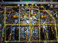
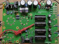
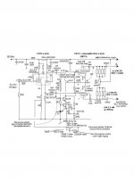
In short, I regulary use this earth matrix concept for power amps with AC transformers & chokes in close proximity, basically to avoid circulating currents in the chassis that can give rise to miniscule AC potentials between differing earth points, and since the noise figures of audio amps requires very low hum figures, a safe way is to use a busbar earth internally which avoids chassis potentials. The "earth matrix" loop is lifted off via insulated standoffs and earthed at the furthest point away from the power components at the input stages, (shown as crosses) roughly equicentral if stereo stages are being constructed. Obviously if a mono block is used this is considerably smaller.
See pic, follow yellow line which behind this is the copper bus. This one is solidly constructed with 4mm copper wire and this requires a hefty soldering iron. Many amps in the past used 2.5-3mm copper wire. The photo is another amp built on exactly the same lines as the previous 250+250W.
Strictly really one could do away with a ally chassis as used here, but since I use a 1kW switched mode power supply, this requires every particle of shielding and supression available, and the earth matrix is a pretty reliable method.
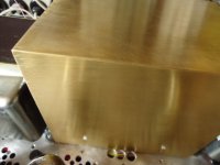
Metalworking tips:- Also shown is the brass lid for the transformer/switchmode unit; 0.5mm brass sheet from a hardware store, plus a hardmetal scriber, use a flat surface sheet and clamp metal ruler where desired bend is required and repeatedly keep scribing in the same grove on the inside until it can easily bend without breaking. Since it is thinner at this line, the inside can be reinforced by soldering.
richy
Attachments
@richwalters
Are these KT90 from EI?
I had some reliablity issues with KT90 from EH and changed to KT120.
EH KT90's used. I have found them consistent in my studio system. A friend was using KT120's in his and he wasn't happy..that makes the choice rather awkward as no others are suitable. I wouldn't dare run todays KT88's in UL at 600V.
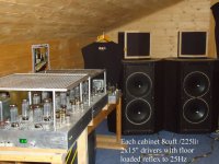
The two power Williamson concept 500W amps shown left in pic have lower power saving settings 20W;50W for easy listening at 200V & 300V B+; For my bass guitar and octave shifter work, 600V at 65mA Iquies per tube is the norm without problems.
This system is capable of not only destroying ears and vibrating any socket loose but also striplights in arenas. This is the reason that the internal construction of these amps does require careful point to point work with generous soldering and support. Hence the input tube clamps. The loudspeakers too require internal bracing and this must be done correctly.
Keep listening up !
richy
Attachments
In short, I regulary use this earth matrix concept for power amps with AC transformers & chokes in close proximity, basically to avoid circulating currents in the chassis that can give rise to miniscule AC potentials between differing earth points, and since the noise figures of audio amps requires very low hum figures, a safe way is to use a busbar earth internally which avoids chassis potentials. The "earth matrix" loop is lifted off via insulated standoffs and earthed at the furthest point away from the power components at the input stages, (shown as crosses) roughly equicentral if stereo stages are being constructed. Obviously if a mono block is used this is considerably smaller.
See pic, follow yellow line which behind this is the copper bus. This one is solidly constructed with 4mm copper wire and this requires a hefty soldering iron. Many amps in the past used 2.5-3mm copper wire. The photo is another amp built on exactly the same lines as the previous 250+250W.
Strictly really one could do away with a ally chassis as used here, but since I use a 1kW switched mode power supply, this requires every particle of shielding and supression available, and the earth matrix is a pretty reliable method.
Metalworking tips:- Also shown is the brass lid for the transformer/switchmode unit; 0.5mm brass sheet from a hardware store, plus a hardmetal scriber, use a flat surface sheet and clamp metal ruler where desired bend is required and repeatedly keep scribing in the same grove on the inside until it can easily bend without breaking. Since it is thinner at this line, the inside can be reinforced by soldering.
richy
Looks like a ground plane, without the plane. I ll keep it in mind, thanks.
EH KT90's used. I have found them consistent in my studio system. A friend was using KT120's in his and he wasn't happy..that makes the choice rather awkward as no others are suitable.
Interesting, my experience with KT120 is more positive. And in AB2 Mode I have got 200W out of a pair (UL mode with separate G2 winding)
Interesting, my experience with KT120 is more positive. And in AB2 Mode I have got 200W out of a pair (UL mode with separate G2 winding)
The problem is more field time results are needed vs. operating conditions.
With NewSensor I was badly letdown by their TungSol 6550's New Ed (coke bottle) with 2000 hrs being the end date. 470V 70mA quiesAB1; I believe others also spotted the fact that this class of tubes simply don't like being pushed over the 33W dissip ballpark, contrary to the data sheets. Many users also mention that the 6550 is part-power classed to the KT88; how wrong it turns out to be.
However, I remember in 1967 when KT88's were used in UL amps at 600V with a quies at 60mA without any fuss. Worst still, many designed amps were put in racks and it was the question of electrolytic cap reliability which was the issue, not tubes. That has now turned around as electroytics in optimum positions are lasting far longer. I wouldn't operate in those conditions now.
I turned to the EH KT90, which in some ways behaved how an original KT88 used to be, i.e take punishment. I had thought about the EL156 group, but again not enough field tests with the chinese octal version and this tube is pricy with no second source.
richy
Progress progress
Progress progress, when I’m not working or being married.
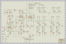
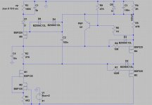
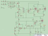
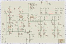
The driver stages have now been put onto a board and tested; I've posted the hopefully final optimised version and a picture of the board. The screen shot of my scope shows the beginning of obvious clipping (‘bottoming out’) from the board at about 155V p/p, given 500V B+ on the KT88’d bias will be about -57V so that’s plenty. More to the point at 100V p/p THD of the driver is less than 1% which will be swamped by the output stage.
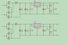
I’m going to regulate the B+, and hence the bias as well. I’ve tested the B+ regulator posted based on the Gary Pimm / Swenson circuit at 500V 500mA out; there are some changes from the Gary Pimm design because I could never get it stable. I’m going to use a Hammond 379WX for the B+, bias and KT88 heaters and a Hammond 266N12 for the driver heaters. I’ve modelled the dissipation in the MOSFETs at around 60W using the 425-0-425V taps on the Hammond so I’ll be using a 0.2C/W Fischer forced air heatsink but I’ll run the fan at a lower than rated voltage to keep it quiet. I’m going to earth the heatsink with the MOSFETS on insulators and a fuse between them and the 850W transformer in case the insulation pad ever fails.
I’ve modelled a negative version of the Gary Pimm / Swenson as shown on the screen shot of LTSpice and I’m waiting the MOSFETs to test it. The driver stages will have DC heaters and I’ve tested the attached design using Linear LDOs from a 6.3V heater.
I will also need a 12V PSU to drive the fan for the heatsink and I’m going to use that to run some protection circuitry (soft start on the KT88 heaters and bias protection) so there will be five PSUs to worry about.
I imagine it will take me six months to get all that on another board and test it…
Progress progress, when I’m not working or being married.
The driver stages have now been put onto a board and tested; I've posted the hopefully final optimised version and a picture of the board. The screen shot of my scope shows the beginning of obvious clipping (‘bottoming out’) from the board at about 155V p/p, given 500V B+ on the KT88’d bias will be about -57V so that’s plenty. More to the point at 100V p/p THD of the driver is less than 1% which will be swamped by the output stage.
I’m going to regulate the B+, and hence the bias as well. I’ve tested the B+ regulator posted based on the Gary Pimm / Swenson circuit at 500V 500mA out; there are some changes from the Gary Pimm design because I could never get it stable. I’m going to use a Hammond 379WX for the B+, bias and KT88 heaters and a Hammond 266N12 for the driver heaters. I’ve modelled the dissipation in the MOSFETs at around 60W using the 425-0-425V taps on the Hammond so I’ll be using a 0.2C/W Fischer forced air heatsink but I’ll run the fan at a lower than rated voltage to keep it quiet. I’m going to earth the heatsink with the MOSFETS on insulators and a fuse between them and the 850W transformer in case the insulation pad ever fails.
I’ve modelled a negative version of the Gary Pimm / Swenson as shown on the screen shot of LTSpice and I’m waiting the MOSFETs to test it. The driver stages will have DC heaters and I’ve tested the attached design using Linear LDOs from a 6.3V heater.
I will also need a 12V PSU to drive the fan for the heatsink and I’m going to use that to run some protection circuitry (soft start on the KT88 heaters and bias protection) so there will be five PSUs to worry about.
I imagine it will take me six months to get all that on another board and test it…
Attachments
Xperse
Different avenues;
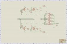
I've gone Williamson diff with 12BY7A's; which has active pull down to deal with Miller effect; o/p voltage swings same with B+ only 360V, tube currents higher; o/p Z around 2K.....all kinds of comparisons can be made. 20dB gnfb
See driver pic: This circuit can handle a 1nF cap connected to each output per Miller simulation; somewhere I'll dig the squarewave graph out.
At the moment I'm in the process of converting and copying all old drawings from 32 bit to my new 64bit machine: Not everything goes quite as it should do.
Looking at your grid leaks; the effective output AC resistive shunt load on each cath follower driver is a little higher than the driver cathode resistor value of 33K.
With the Williamson I've kept this ratio wider; so with this active driver stage, it shunts the Miller-effect better. Becareful with this type of stage as the bandwidth is considerably higher than the cathode follower; thus the Miller effect sees the 33K resistor in series; and can only be "pulled down" the value of this cathode resistor. My Williamson has -3dB point at 70Khz ...but as you know it all depends on the o/p tranny quality.
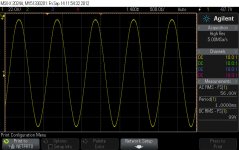
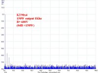
I've posted the spectrum at 150W o/p.. it's clean. The other which I'm working with is at 250W o/p, at slightly higher thd, onset clipping.
KT90's at 600V, will parallel p-p will reach this power region; there is enough drive.
Expect 20% less power with 88's. Some makes of these won't be happy at 600V...so I'm with KT90's.
The remainder of the story is with the power supply. For this o/p power, my dual/stereo amp needs stabilised 600V at 1kW rating reserve. This contains an active PFC boost converter and is beyond forum work.
HINT; If one doesn't to see switchmode power supply HF harmonics in the audioband spectrum, i.e lower than -80dB down; a complete understanding of EMI issues and magnetics is vital.
Dunn'a want to do this way ? Stay with simple passive components.
If one tabulates and documents the results as one designs this; you have the silk purse in understanding it all. Alot of work, but EXcel and other programs are worth it.
richy
Different avenues;
I've gone Williamson diff with 12BY7A's; which has active pull down to deal with Miller effect; o/p voltage swings same with B+ only 360V, tube currents higher; o/p Z around 2K.....all kinds of comparisons can be made. 20dB gnfb
See driver pic: This circuit can handle a 1nF cap connected to each output per Miller simulation; somewhere I'll dig the squarewave graph out.
At the moment I'm in the process of converting and copying all old drawings from 32 bit to my new 64bit machine: Not everything goes quite as it should do.
Looking at your grid leaks; the effective output AC resistive shunt load on each cath follower driver is a little higher than the driver cathode resistor value of 33K.
With the Williamson I've kept this ratio wider; so with this active driver stage, it shunts the Miller-effect better. Becareful with this type of stage as the bandwidth is considerably higher than the cathode follower; thus the Miller effect sees the 33K resistor in series; and can only be "pulled down" the value of this cathode resistor. My Williamson has -3dB point at 70Khz ...but as you know it all depends on the o/p tranny quality.
I've posted the spectrum at 150W o/p.. it's clean. The other which I'm working with is at 250W o/p, at slightly higher thd, onset clipping.
KT90's at 600V, will parallel p-p will reach this power region; there is enough drive.
Expect 20% less power with 88's. Some makes of these won't be happy at 600V...so I'm with KT90's.
The remainder of the story is with the power supply. For this o/p power, my dual/stereo amp needs stabilised 600V at 1kW rating reserve. This contains an active PFC boost converter and is beyond forum work.
HINT; If one doesn't to see switchmode power supply HF harmonics in the audioband spectrum, i.e lower than -80dB down; a complete understanding of EMI issues and magnetics is vital.
Dunn'a want to do this way ? Stay with simple passive components.
If one tabulates and documents the results as one designs this; you have the silk purse in understanding it all. Alot of work, but EXcel and other programs are worth it.
richy
Attachments
6SN7 Driver with PPP KT88 - Change of plan!
Having built two of the circuit I posted I was intermittantly unhappy with the sound - great a lot of the time but unpredictably muddy, and that not obviously driven by type of music / output power levels etc.
This was traced eventually to the regulated 'Swenson' type B+ PSU being dynamically unstable - manifesting as 30 or so khz 'relaxation' oscillations but only at specific current loads and input / output voltage differentials. So the problem was coming and going in an almost random way with vairiations in line voltage etc - I tracked it down eventually by just leaving a scope on the B+ power rail and playing music. I couldn't model the oscillation in Spice, tried the recommended strategies with this type of circuit to squash it and just ended up surrendering!
So complete rebuild of PSU - changed to 2 x '21st Century Maida' regulators sharing the load. I also changed the Sowter UO71 OPT to a Lundahl LL1693PP as an experiement and found a substantial increase in open-loop bandwidth, so I stuck with the Lundahl.
Here's perfomance now at 510V B+, 55mA Electroharmonix KT88's (n.b, lovely pale blue glow in the dark...) and with 13dB GNFB with a gain of about 26dB for the amp as a whole:
-3dB 15Hz and 80kHz, 20W out 8R pure resitive load
Z-weighted THD <0.1% at 2kHz 20W out, 0.2% at 100W out, clips at 138W.
Modulation of the B+ power rails is <1V at full output (limits of noise on my scope with a x100 probe), 10Vp/p 10kHz square waves are very clean into a 8R load, and there is modest 140kHz ringing into 8R / 0.47u.
I have made 2x PCBs for the PSUs (all regulated: 2x510V @ 300mA, -70V @ 100mA, and 2x 6.2V @ 1.2A) and the driver. I am now sorting out some protection circuits, and then the amps will then go in the boxes. Then I will sit back...
I can see how a lot of amps end up 'boat-anchors' - a test build of one is a large commitment, let alone two, and until you have built two how do really know what it is going to sound like...? I guess I could have found this problem through the right testing though ...
Xpersephone2
-3dB 15Hz and 80kHz, 20W out 8R pure resitive load Z-weighted THD <0.1% at 2kHz 20W out, 0.2% at 100W out, clips at 138W.
.......................
Good work; but I'm curious: -3dB at 80Khz pricked my ears..but I'm going to be awkward and ask you for a pic of a 10Khz square wave at the 10W level.
richy
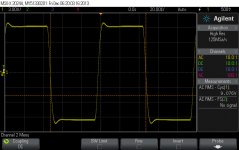
Well done: that slight "pip" on the first waveform is a notch phase advance or is it ? I was fooled by a double earth that is moving the scope probe ground changed the waveforms.
Users may note that the upper frequency response strips that of many commercial winds, around considering the power.
Lundahl is a multisection design, as is the 18 sect Majestics I used for the 250+250W where the sheer size (11kg each) places a constraint on the leakage parasitics and maximum HF response, where in reality 55Khz was the upper point.
Not last of the nasty checks I would stipulate, is one of confidence in ones design and that is mentioned in MJ book Valve amps 4th ed p.469 section The power amplifier stability margin.
How much can one reduce the global nfb before any form of instability is noticed ? The first thing in approaching this test is care mighty care over it. In my design I reduced B+ down to half, (although it changes the o/p operating points somewhat) but importantly keep the input/ driver stages at their nominal voltages.
If one has designed the amplifier correctly; (small 1Khz signal on input, jot loop gain reference i.e set 0dB without global nfb loop connected, and then measure difference with the designated global nfb value (jot this down).
Then further reduce the global nfb value (over the designated global feedback value) at a point that HF instability is spotted again, jot down difference and one has the simplistic so-called stability margin. If both HF & LF instability arrive the same then one has an optimised amp. (quite rare)
LF instability will come in the form of a very low subsonic freq 1-5Hz and gradually increase in amplitude til the whole output stage rocks...be detectful on this extreme straining condition well below the output transformer cut off and take upmost care if one insists on using the full B+. (I wouldn't risk it myself)
richy
One can take the design further, phase response and so on.
Phase margin & Ultralinear taps
Just looking at my notes the HF response open loop is insane: -6dB is somewhere north of 110kHz!
Testing stability margins has been on my mind, bearing in mind my previous problems. I need to do some serious reorganisation to provide a reduced B+ on the output stage, a combination of work and holiday means I won't be starting that until mid Jan of 2014. I can only guess where doing these tests at full B+ might lead, but there's a lot of expensive components in this beast and I'd rather not find out!
During some earlier testing I had up to 6dB more feedback applied without any obvious signs of instability so I'm not in a bad place I think. What kind of stability margin should I be looking at?
The Lundahls have been configured for 50% Ultralinear taps by the way - does this impact anything versus the usual %?
The square wave response is informative; a peak in the response. The beauty of being in a situation of frequency generosity that is easiest to slew the response down, enhancing stability.
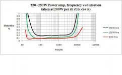
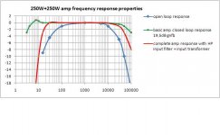
The 250+250W Williamson 40% ULtaps, 18 sect transformer using KT90's was carefully worked out; as I use this amp for both HiFi and Tyros keyboard work where the HP 15Hz filter is imperative although the each amp can take 250W per ch at this frequency. The dynamic range of digital instrumentation will test ANY amp for it's loop settling and clarity to avoid muddling.
Open loop gain both ident around 19,5dB; global nfb can be increased by 14dB before instability sets in at both frequency extremes.
Don't take my design as reference; as lit will show the Philips/Mullard 5-20 used 30dB loop gain and the global nfb could be increased to 40dB before instability sets in (sounded tight) ; in dire contrast to the Mullard 5-10 where nominal 26dB is used, and liable to oscillate anywhere over 29dB. No hard and set rules.
One issue to bear in mind is that those early near class A amps were quite stable with single cone fullrange speakers with long cables, and as 12dB crossovers appeared then the stability issues came too.
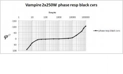
Enclosed is pic of phase shift and overall response.
I contratulate you in having got a real workable specimen; optimisation can go further; the other nasty is how the global nfb loop reacts to the dynamic and amplitude signal response; especially important when digital instrumentation (Tyros 4) is used and will test ANY tube amp for it's loop settling when the output impedance is higher than for solid state amps. Fortunately for the Williamson design those interstage coupling caps that exit the concertina is an easy access point and change is highly responsive. In most cases it's simple RC optimisation of the poles; my method is coincidental; that it matches Steinmetz's law that at the o/p tranny designed LF cutoff; aim for 1.5% thd F1 at full power at that low frequency, and the transient response considered optimised.
There is alot more.
Happy building
richy
The 250+250W Williamson 40% ULtaps, 18 sect transformer using KT90's was carefully worked out; as I use this amp for both HiFi and Tyros keyboard work where the HP 15Hz filter is imperative although the each amp can take 250W per ch at this frequency. The dynamic range of digital instrumentation will test ANY amp for it's loop settling and clarity to avoid muddling.
Open loop gain both ident around 19,5dB; global nfb can be increased by 14dB before instability sets in at both frequency extremes.
Don't take my design as reference; as lit will show the Philips/Mullard 5-20 used 30dB loop gain and the global nfb could be increased to 40dB before instability sets in (sounded tight) ; in dire contrast to the Mullard 5-10 where nominal 26dB is used, and liable to oscillate anywhere over 29dB. No hard and set rules.
One issue to bear in mind is that those early near class A amps were quite stable with single cone fullrange speakers with long cables, and as 12dB crossovers appeared then the stability issues came too.
Enclosed is pic of phase shift and overall response.
I contratulate you in having got a real workable specimen; optimisation can go further; the other nasty is how the global nfb loop reacts to the dynamic and amplitude signal response; especially important when digital instrumentation (Tyros 4) is used and will test ANY tube amp for it's loop settling when the output impedance is higher than for solid state amps. Fortunately for the Williamson design those interstage coupling caps that exit the concertina is an easy access point and change is highly responsive. In most cases it's simple RC optimisation of the poles; my method is coincidental; that it matches Steinmetz's law that at the o/p tranny designed LF cutoff; aim for 1.5% thd F1 at full power at that low frequency, and the transient response considered optimised.
There is alot more.
Happy building
richy
Attachments
Last edited:
Burning down the house...
I managed to work out a quick way to separately power the output stage - a builder's site transformer plugged into a variac... so with B+ now reduced to 220V, the open loop gain at 1kHz=41.9dB which is unchanged from the full 520V B+. All of these tests are with 1W output sine wave and with driver B+ still at 520V.
R31=10K (design value), gain = 29dB, 13dB GNFB
R31=1K, gain=13dB, 29dB GNFB, no stability issues.
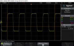
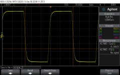
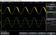
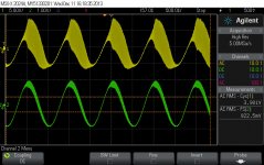
R31=800R, intermittent oscillation (see scope pictures, yellow is output, green is input), at 200KHz and 0.7Hz simultaneously. Gain=12dB.
R31=700R, rock and roll time, everything going crazy. 500V B+ would have been a spectacular ...
If I use a square wave it seems to better excite the oscillation modes. Here for a 1kHz input I begin to get the same 0.7Hz LF oscillation at R31=1.2K and the HF kicks in at R31=1K, so the LF instability wins marginally.
Increasing the phase lead capacitor did nothing to improve the phase margin, and neither did increasing the cap defining the dominant HF pole after the triode input. I also increased the B+ to 280V and repeated the above unchanged. So I guess I am close to 'critically damped', with all my ducks lined up and a phase margin of 16dB .... (deep sigh of relief at maybe not having wasted $10k and 100's of hours of my time to get this far)...
I managed to work out a quick way to separately power the output stage - a builder's site transformer plugged into a variac... so with B+ now reduced to 220V, the open loop gain at 1kHz=41.9dB which is unchanged from the full 520V B+. All of these tests are with 1W output sine wave and with driver B+ still at 520V.
R31=10K (design value), gain = 29dB, 13dB GNFB
R31=1K, gain=13dB, 29dB GNFB, no stability issues.
R31=800R, intermittent oscillation (see scope pictures, yellow is output, green is input), at 200KHz and 0.7Hz simultaneously. Gain=12dB.
R31=700R, rock and roll time, everything going crazy. 500V B+ would have been a spectacular ...
If I use a square wave it seems to better excite the oscillation modes. Here for a 1kHz input I begin to get the same 0.7Hz LF oscillation at R31=1.2K and the HF kicks in at R31=1K, so the LF instability wins marginally.
Increasing the phase lead capacitor did nothing to improve the phase margin, and neither did increasing the cap defining the dominant HF pole after the triode input. I also increased the B+ to 280V and repeated the above unchanged. So I guess I am close to 'critically damped', with all my ducks lined up and a phase margin of 16dB .... (deep sigh of relief at maybe not having wasted $10k and 100's of hours of my time to get this far)...
Attachments
Phase & Gain Versus Frequency
I've also done so decent measurements of gain and phase (spreadsheet attached). Conditions here are full B+ with the design GNFB at constant output with sine wave input.
Volts are RMS from a Fluke 8846A, my scope measures phase directly
Mr Lundahl clearly knows his stuff up there in Sweden!
I've also done so decent measurements of gain and phase (spreadsheet attached). Conditions here are full B+ with the design GNFB at constant output with sine wave input.
Volts are RMS from a Fluke 8846A, my scope measures phase directly
Mr Lundahl clearly knows his stuff up there in Sweden!
Last edited:
- Status
- This old topic is closed. If you want to reopen this topic, contact a moderator using the "Report Post" button.
- Home
- Amplifiers
- Tubes / Valves
- KT88 Parallel Push Pull