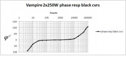
Phase stuff...mine looks as per attachment.
Rule: The phase difference of 180° equates to 12dB/oct.The trick is to make sure the loop gain vs. frequency doesn't drop more than 10dB/oct, in that part where it passes from +10dB to -10dB through the point where the amplifier gain is unity, the amp will be stable. That's why the response must be known beyond both audible parts of the spectrum.
This can be awkward stuff to grasp..the Bode plot, Nyquist RH planes is highly relevant amplifier design stuff.
The enclosed graph gives the evidence of symmetrical stability, however excel has somehow omitted the all important dB scale on the LHside.
One can if devoted create ones own dummy phaseshift load with RCL all in series or lumped.
Radiotron hd bk 4th ed p.356 stability. You may not like it but it's a highly relevant examination point !
richy
Attachments
Rich ... Hmm .. downloaded the Radiotron ... a very challenging read. I need an Engineering Mathematics textbook and study time. I have a long holiday coming up!
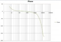
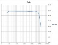
Of the specified criteria I do have about 10dB / octave HF gain roll-off. However I have the following problems, at least I think, looking at the attached phase and gain plots:
1. The most obvious thing (to me .. I may be wrong!) is that the LF response is too extended and rolls off too slowly. If I increase C4 to 390pF and C17 to 330pF the HF oscillation sets in at only 8dB closed loop gain (ie 34dB GNFB), however the LF oscillation sets in at about 12dB, and the LF roll-off is only at a 6-8dB slope.
2. I am hence going to try reducing the bias resistors - almost halving them to 33K and / or decreasing the coupling cap value. That will give me more LF roll-off, however I am guessing that the slope will still be a problem ... is that why you have a high pass input filter on your amp? Lowering the bias resistors to 33K will also give me under 50K in the bias circuit ..I could try KT120s at some time if I ever wanted to.
3. Closed loop the amp still has appreciable gain at 200khz at phase angles over 180 degrees. I can't see how to fix this, if I increase C4 I get less HF gain but more phase shift at a given frequency, I guess I could put capacitors across the LTP load resistors to give a second time constant but then I will get a steeper HF roll-off and go over the 10dB slope ... or am I misunderstanding things?
Are there any truly unconditionally stable tube amps? It strikes me that there are so many conflicting requirements, phase shifts, etc that there is always going to be a problem somewhere. Particularly if you have not been building them for years.
This all seems so close and yet so far from being finished!
Attachments
Progress
A bit of thinking and component value tuning ... tried a few things that did not work, and a few that did..
I'm not clever / devoted enough to make all the 'book' stability criteria, but have optimised values without changing anything fundamental and achieved significant improvements in the phase margin.
Reducing the grid resistors has cured the LF oscillation which previously set in at around 28dB GNFB. Increasing the open loop HF roll-off allowed a further increase in stable GNFB. The amp is now stable with 33dB of GNFB taking an open loop gain of 42dB to a closed loop gain of only 9dB, and oscillates at HF if feedback is further increased. I have increased the design feedback slightly to 16dB so there is 17dB of crude phase margin. I have also added a high pass input filter as LF response was pointlessly extended.
Various discussions on this forum seem to suggest that with that level of phase margin I should be safe into any conceivable load...
As a trial I have run for 6 hours with music input into a 8R resistor +10R/0.22u in parallel connected through 10m of coiled cable and with peaks clipping at 140W, and seen no signs of instability.
Very grateful for the help so far and always grateful for suggestions!
Attachments
What you have achieved is a warning shot for those not so proficient at circuit design- to follow a design that has been tested with time.; I found as you did that a superlative performing driver stage often has to be slugged by a poorish front end just to slew limit the wretched o/p tranny deficiencies when the loop is closed. The values of RC across the 1st stage anode often says it all. It is a correct design when the driver and o/p stages outperform the input.
Probably the most temperamental design I first built was the 3 stage design of the KT88-50 around 1958.. an astoundingly simple and good sounding performer despite the see-saw phasesplitter and other drawbacks. I don't know of another design that sounds similar.
The long speaker lead test is a nasty capacitive load, however, later in years when I returned just to check out my big amps, the desire to tinker and trim the values is always there. You mentioned that I put a 3rd order HP filter at the loudspeaker reflex below port tuning frequency, that is to avoid severe out of phase loading when used with octave shifters. Remember, below reflex port resonance, the 24dB/oct acoustic cutoff with such systems presents a severe cone unload, forcing against the suspension with honking..
My goodness there's alot to know.
richy
Progress progress
There is indeed far too much to know...
Moving onto watchdog / protection type circuits, I think I am on the home run of design!
Here's what I am trying to protect the amp against and the design response to it:
1. Open circuit outputs - 470R resistor across OPT secondary and reverse-biased diodes across the output KT88s to kill flyback voltages. I thought about gas dischrge tubes, does anybody have any experience of these?
2. Startup surges resulting in fuse values being too high and not protecting amp against blow-ups - I have B+ supply soft-start from the '21st Century Maida' regulator used. Also PTCs in both legs of power transformer primary, and switched out of circuit by relay 1 second after turn on.
3. B+ regulated PSU overheat -temperature sensor on heatsink, overheat shuits down amp.
4. Output tube shorts, bias voltage loss etc - all trapped by comparator measuring voltage across 10R KT88 cathode resistors, over voltage shuts down amp.
5. Brown-outs, mains power switch being flicked on / off etc producing surges, PSU blowups etc - amp has enforced time constants on switch on AND switch off . So the on/off switch has to be on for at least two seconds to trigger startup of the amp, and for thirty seconds after power has been removed the amp cannot be tunred back on.
6. I obviously have fuses in the primary of the power transformer and the primary of the OPT.
I have achieved all of this with a very simple set of circuits based around a CMOS flip flop, some voltage comparators and a couple of power relays. Can anybody see any potential problems I have not picked up on in the watchdog / protection circuits?
I now have new boards being made for the driver, and the PSUs. I am telling myself that I am dangerously close to finishing, leaving aside metalwork!
Important is the "wait before state", that is a watchdog time out must have a delay as tube stuff does take some time to settle. In my amps using a 1kW SMPS, using opto's as interfaces as the vicinity around the switches is RFI high. Using SS, B+ ramp up can be allied with tube warm up, and the important interlock should quickly react if the negative bias supply fail as 8x KT90's become expensive. As you have mastered the SS, ingenuity has no bounds, but designing analogue, one can get the fail safe operations right. Once mastered, one can confidently consider oneself as a system.s engineer.
Generally I am against servo surveillance, i.e monitoring cathode currents, unless very long time constants and integration is used and the reflected current leakage inductance spikes will appear on the cathodes. This is the reason that wirewounds be used as cathode resistors as metal oxide/film resistors cannot handle transient stuff..
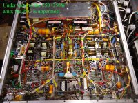
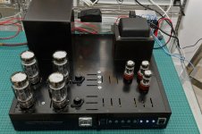
Pic of 250+250W....I'd admit there's alot of protection circuitr in this chassis as I live in a wooden house, but the important issue is that the protection works ! The fuse in each centre tap o/p primary should be a quickblow type and I used 800mA-1A to deal with transients.
richy
Generally I am against servo surveillance, i.e monitoring cathode currents, unless very long time constants and integration is used and the reflected current leakage inductance spikes will appear on the cathodes. This is the reason that wirewounds be used as cathode resistors as metal oxide/film resistors cannot handle transient stuff..
Pic of 250+250W....I'd admit there's alot of protection circuitr in this chassis as I live in a wooden house, but the important issue is that the protection works ! The fuse in each centre tap o/p primary should be a quickblow type and I used 800mA-1A to deal with transients.
richy
Attachments
Running with KT120s
I will finish this amp this year.. sadly I have started thinking that I need to learn more and figure out how to make a better one! I have however disciplined myself not to start trying to change the design I have already reached.
Design of the case is finished, using Front Panel Designer. As I am waiting for that to manufacture I decided to experiment with some KT120s, which I had in mind to do. My major motivation was simply to use tubes that were hardly breaking sweat rather than to get more power. The amp has low value grid leaks so the use of the KT120s is safe.
At 490V B+ the KT120s biased at -53V and the amp gives 145W at clipping, THD is 0.2% / 1kHz at 28V RMS /100W. KT88s needed about 30V more B+ for the same output power.
I thought about higher B+ with the 120s and then thought again, somewhere on this forum I read what seemed like excellent advice 'getting the last few dB out is usually what blows things up' and there's quite a lot of money on the table.
I think I shall stick with the KT120s, they seem to have a decent reputation and I see them in a lot of high end gear...
I got the Kt120 from Hotrox in the UK. The quad I purchased were very well packaged and matched.
I started them out at 50mA plate current and this increased by about 60% in the first half hour of operation, I was a little worried. All tubes ended up biased within a half volt.
I started them out at 50mA plate current and this increased by about 60% in the first half hour of operation, I was a little worried. All tubes ended up biased within a half volt.
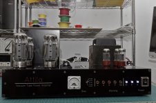
Finally we are nearly there!
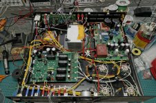
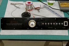
My wife called this 'Atilla' ... as in something dangerous that occupied a lot of territory.
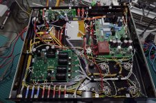
The board at the back is the watchdog / soft start, the front left the driver and the PSU is on the right. I thought for one awful moment I had tried to make it too small but we have just about clung to the right side of merely huge.
This weekend I should finish the first of two and power up.
My wife called this 'Atilla' ... as in something dangerous that occupied a lot of territory.
The board at the back is the watchdog / soft start, the front left the driver and the PSU is on the right. I thought for one awful moment I had tried to make it too small but we have just about clung to the right side of merely huge.
This weekend I should finish the first of two and power up.
Attachments
I built PPP units. I retired them to the shelf because 60 watt units really do not sound much louder than the 140 my blocks put out with my speakers. Power is necessary for the inefficient units like ribbon drivers. If you do not need it, go with standard PP designs. You will save considerable weight, expense, and heat.
Nevertheless, I get 0.7% THD at 1k open loop with my PPP units. This is 140 watts into an 8 ohm resistive load. Closed loop the THD drops to 0.15% with 12dB of feedback.
Nevertheless, I get 0.7% THD at 1k open loop with my PPP units. This is 140 watts into an 8 ohm resistive load. Closed loop the THD drops to 0.15% with 12dB of feedback.
Hi BRS,
I've ended up almost exactly where you have in terms of power output / THD / GNFB. Is it worth it ? - I have big medium efficiency speakers which drink current at low frequencies. So maybe. Building something like this is certainly a massive undertaking for somebody with a full time job, I might not have done it if I had known exactly how hard it would be.
I've ended up almost exactly where you have in terms of power output / THD / GNFB. Is it worth it ? - I have big medium efficiency speakers which drink current at low frequencies. So maybe. Building something like this is certainly a massive undertaking for somebody with a full time job, I might not have done it if I had known exactly how hard it would be.
0.7% THD is probably not audible, depending upon the harmonics that consist of it (odds are the worst and the hardest to eliminate). I just added a small amount of feedback to my units so I can boast to my friends that I beat McIntosh using Dynaco and Mullard based circuit topologies. I also wanted control of the input sensitivity. Running open loop ensures greater stability. If a closed loop design is chosen, a stability analysis is necessary to allow for the design of a proper compensation network. Keep in mind that the pole locations change depending on the load, or lack thereof.
I had an entire course on control theory at RIT.
Distortion always will increase significantly with frequency, especially at frequencies above 10k. Poor quality iron always exacerbates this problem. That is largely moot because harmonics up there are inaudible (not to your dog though). Furthermore, there is little musical information in most audio programs up there. Look at power spectral density plots.
Earth shaking bass is easier to attain with less power in bass reflex enclosures. Ribbon drivers and acoustic suspension designs generally will drink lots of amps. I simply steer my way around this problem by selecting good sounding speakers that are efficient. My B&W 683's disturb the neighbors with less than 35 watts.
I will admit, building my PPP units was a learning curve. It is in my opinion definitely worth it to undertake, even with a full time job, for the simple reason that it makes you a better engineer.
I have an ambition to 'completely solve' the GNFB conditions for unconditional or at least maximal stability by reducing a design to single time constant circuits and solving using Mathlab or whatever. A renowned tube amp 'old timer' advised me it would be a fruitless quest, the OPT would defy modelling and the solutions would be of little value. Cue controversy ?
?
The best advice I received was to optimise the GNFB with the outputs run at a reduced B+ and maximise the simplistic stability margin. That and avoid overlapping poles. I have an amp stable with up to 33db of GNFB into a 8R load, so I am very safe with the 16db I have applied.
I am a systems engineer in a different discipline, and building an amplifier of this scale is a formidable task. I have considerable financial resources and it has come close to defeating me. The most complex task has actually been the watchdog / soft start circuitry. I have learnt a huge amount doing this, and of course are planning something else now - a single ended 13e1 amp!
? The best advice I received was to optimise the GNFB with the outputs run at a reduced B+ and maximise the simplistic stability margin. That and avoid overlapping poles. I have an amp stable with up to 33db of GNFB into a 8R load, so I am very safe with the 16db I have applied.
I am a systems engineer in a different discipline, and building an amplifier of this scale is a formidable task. I have considerable financial resources and it has come close to defeating me. The most complex task has actually been the watchdog / soft start circuitry. I have learnt a huge amount doing this, and of course are planning something else now - a single ended 13e1 amp!
The best advice I received was to optimise the GNFB with the outputs run at a reduced B+ and maximise the simplistic stability margin. That and avoid overlapping poles. I have an amp stable with up to 33db of GNFB into a 8R load, so I am very safe with the 16db I have applied.
That amount of GNFB is about the limit. My Williamson Power I use 20dB GNFB with 16dB stability overhead, that summed up to 36dB before some instability protest begins esp when the upper response -6dB roll off is around 50Khz. This requires careful thought.
Usually, I design so the poles of LF & HF instability are fairly close in the level taken to create instability at the frequency extremes. The High end instability is somewhat layout and proximity sensitive when unscreened tubes are used at the input. This is a perfect reason to design power amps around the 0dBu level (0.77V rms) for full output with the level of GNFB used..
richy
Finally - Finished .. one monobloc
Finally I have finished one monobloc... was it worth it? I won't know until I've finished the second one! I was tormented by self-inflicted wounds:
1. Time wasted on fixing spurious resets in the fairly complex protection circuitry which ultimately came down to poor decoupling, and excessively high value pullup resistors on the logic controlled startup / watchdog circuitry. This was not apparent on the breadboard, only when I put the amp with everything up close and personal in the case. After a few easy fixes did for most of the problem I was left with something intermittent and related to the occasionally very high humidity where I live and a very sensitive SCR. Aagh...weasels ripped at my flesh...
2. An entirely stupid earth loop, having thought I had been ruthless about star grounding this left me with 10mV RMS mains hum with a nasty treble lift giving it an audible buzzing edge (capacitor charging pulses). This only took me a few hours to find and now I have noise down to <0.5mV RMS with the input short-circuited, now much quieter than my breadboard which had about 3-5mV noise.
I have hopes the amp is a respectable subjective performer, measuring 1kHz / 50W output THD + N under 0.05% Z-weighted, and 0.3% at 150W, with 3% THD at just short of 170W clipping into 8R. The KT120 quad are being operated at 490V B+ 80mA fixed bias.
Number 2 should be far quicker.. work permitting...
Attachments
Hello Mr XP,
Well done on your noise and distortion performance as well.
I am interested in your protection schemes - what exactly are your tracking and how do you take the amp down in the event of a fault?
Also, those test jacks look great. Who is the manufacturer. - I have been searching for good test jacks for my PP KT88 mono-blocks without much success.
Cheers
Jay
Rich – square waves to follow..
Jay - the protection circuits look at two things:
1. Cathode current across a 10R resistor, independently on each of the four tubes, sensed by a comparator. There is a 5ms time constant on the inputs and over-voltage protection. I have the threshold at 1.6V ie twice the tube bias of 0.8V.
I thought about sensing all sorts of other voltages, but could not see any other fault condition worth shutting down the amp for, that was not reflected in excess plate current (or heatsink temperature).
2. Heatsink temperature sensed on the fan-cooled heatsink (an 0.2C°/W part run at reduced voltage so you can hardly hear it) is set to trip at 80°C.
The rest of the circuitry
3. Runs off an auxiliary transformer. The five fault conditions (4x tube over-current + temperature) are latched by SCR’s, and shut down the main power supply to the amp, so there is a clear fault indication.
4. The logic and timing is done by a CMOS D-type flip flop. The on-off switch is actually switching a flip-flop, which turns the amp on and off via a relay on both poles of the transformer. Any of the five fault conditions toggles the amp off, a SCR is fired which locks the amp out until the power is cycled.
5. After the amp is switched on at the power switch on the IEC socket it will not accept a switch on command for forty seconds. (protects against ‘bouncing’ mains supplies which happen where I live).
6. To start the amp turn on the front panel toggle needs to be switched to on for twenty seconds (to protect against power being switched on and off quickly by the ill-informed in the family!).
7. The power on relay then applies power through a pair of 25R cold resistance NTC thermistors, one in live and one in neutral. These are switched out of the circuit after about five seconds by a second relay. The amp is fused at only 2A fast blow even with the 500VA power transformer which is OK because of the start-up surge being suppressed.
The whole protection board cost $50, cheap and common parts everywhere.
The other protections on the amp are a 560R 5W resistor across the output transformer secondary, and reverse-biased diodes across the output tubes, to give some protection against an open circuit scenario and flyback voltages burning up the OPT.
The test points on the top panel are not quite what you think they are – these are guides for a screwdriver going into the large presets which trim bias current, although they could just as easily be test points. I turned them on a model making lath because I could not find anything suitable!
- Status
- This old topic is closed. If you want to reopen this topic, contact a moderator using the "Report Post" button.
- Home
- Amplifiers
- Tubes / Valves
- KT88 Parallel Push Pull