1 box for PSU 1 box for amplifier in kit88
Hello,
excuse me to disturb you with my stupid question, but I have build a Class A 40W KIT88 (world audio design schematic). I have used the old method and don't used any printed circuit board, just cables. I want to put main transformer (195V-0V-195V 600mA, 0V-27V 100mA, 3,15V-0V-3,15V 9A) and all psu (rectifiers, capacitors, resistors) out of the amplifier box/chassis. So I will have 2 box/chassis, one for amplifier, one for PSU.
For linking (510V/365V/290V/255V/-12V/6,3V) I think I will use Neutrick connectors XLR 3 (KT88 heaters), XLR 5 (6AU6/ECC82 heaters/ ground) and XLR5 (510/365/290/255/-12/ Volts).
Neutrick XLR3 is indicated for 16A, XLR5 for 7,5A.
Do you think it is realistic ? HT could be transmited by Neutrick XLR connectrors ?
Thank you for your help (and excuse my for my english, I'm french).
Best Regards.
Pascal.
Just pray you never meet a professional audio engineer!
An XLR is probably capable of withstanding the stress of HT. Whether you will survive the stress of a professional audio engineer destroying their kit as a consequence is a different matter...
There are lots of multipole connectors that are made especially for your needs before you need to abuse standards. Farnell stock a range of multipole connectors called "Metalok Bantam" which are rated at 750VRMS and 13A, or the "Sealok" range which is rated at 1500VRMS. You can have up to 48 pins if necessary.
Pascal,
I recommend some connectors by EDAC or ELCO (they are compatible).
They look like the picture I have posted.
It is possible to populate only the contacts you require.
They are available in various sizes/
The EDAC website is:
http://www.edac.net/en/Online/online.cfm
I am currentl using one for my power supply - power amp interconnect. It is the 56 way type. This allows some vacant pins for extra insulation, as I am using some pins for 1250 volts and others for 3.25 amps! It also allows for an interlock, which switches off the power supply if the cable is disconnected.
I bought mine from Farnell / RS components (can't remember which one). I remember that the connectors are in the audio section rather than the connector section.
As with all power connectors, it is vital to use female as send, and male as receive.
Cheers,
Attachments
How about CliffCon from Cliff Components They are designed for high-voltage applications.
An externally hosted image should be here but it was not working when we last tested it.
An externally hosted image should be here but it was not working when we last tested it.
Multi vs single
Hi,
The problem with using several connectors is that you must consider the safety aspect if 1 or more is not connected.
That means they all need earths, and where do you join the earths together? What happens to the amp or power supply in the absence of a particular voltage? Is it feasible to design interlocks?
It's easy to find yourself in a situation where safety is compromised for performance.
Cheers,
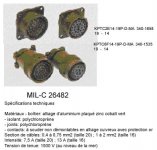
Canon milC26482
Hi,
I think i will use MILC26482 19 pins connector from RS Component. It is very easy to use, i just nead to solder cables on connectors and plug.
In size 16 it's 13A and 19pins is a size 14.
Voltage 1500V.
What do you think of ?
Thank to all.
Pascal.
Hi,
I think i will use MILC26482 19 pins connector from RS Component. It is very easy to use, i just nead to solder cables on connectors and plug.
In size 16 it's 13A and 19pins is a size 14.
Voltage 1500V.
What do you think of ?
Thank to all.
Pascal.
Attachments
Have you considered a 'captive' interconnect? that way you can simply make an umbilical and run it between them. The upside is safety and lower cost, the downside is that if you need to move both the amp and the PSU at the same time, you need 2 people. I've used captives for yonks as the better HV connectors can be a tad expensive here.
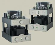
An even better method depending on how you want it to look and arrange the boxes would be to stack the amp and PSU sections vertically. I've done this before too, though my last design had full sides that could be unscrewed for maintenance/mods and a vertical louvre section from and rear to stop my young nephew putting his fingers anywhere he shouldn't (amps were mounted on the floor)
Cary 1610SE
Attachments
Pascal,
The Cannon connectors are perfect. I did consider them, but they were a bit expensive for me!
Male sure to start from the middle pins first") Yes, I've used these at work...
Yes, I've used these at work...
Brett,
Good suggestion. It also limits the cable length. In my case, I ended up with a 1.5m cable necessitating local decoupling caps on every line.
Cheers,
The Cannon connectors are perfect. I did consider them, but they were a bit expensive for me!
Male sure to start from the middle pins first
Yes, I've used these at work...Brett,
Good suggestion. It also limits the cable length. In my case, I ended up with a 1.5m cable necessitating local decoupling caps on every line.
Cheers,
dhaen said:Pascal,
The Cannon connectors are perfect. I did consider them, but they were a bit expensive for me!
Male sure to start from the middle pins first
LOL, me too for some robotics work. Also think about what you're running next to what in the connector and draw out a diagram before you start. It's very easy to make mistakes.
These big multi-poles can often be had from the distributor in your country at a better price than RS/Farnell (but still not cheap like an XLR)
Brett,
Good suggestion. It also limits the cable length. In my case, I ended up with a 1.5m cable necessitating local decoupling caps on every line.
Cheers,
That's two of the reasons I thought about using it. In the last amp I built this way, I even had the final filter caps hanging on brackets from the top plate with the star earth for each stage connected there for each stage via very short wires. All the wiring on the top PSU level was above the bottom deck and the wiring ran directly where it needed to go, so no looms with AC heaters and DC B+ together. To do this you need the sides and front for safety though, but with the sides and front/rear off, it was a breeze to work on. It also takes up less floor real estate.
If you've ever seen a pic of the Trilogy Audio RC211, you'll know what mine look like.
The only pic I could find...
Attachments

Both the MIL-C and the Elco connector are excellent. Broadcasters love the Elco because it's reliable, and I imagine the military had much the same idea in mind for the MIL-C connector. the Elco connector is slightly easier to wire and has a better cable clamp and body, but is more fiddly to plug and unplug.
High voltage umbilical and connectors
Hi all,
Goint to build a 2 box phono amp. Busy with the PSU now.
I know in the past there have been some good posts on this...it's just...well I could not find them anymore...
What do u guys use.
Requirements:
Easy to source...I.e. not stuff I have to steal from NASA..but ye old electronics cornershop type.
600VDC for high voltage. Should be ample?
But also high current for the filament supply.
Preferably not to oddly shaped for easy assembly.
Cheers,
Bas
Hi Bas,
There was a discussion in this thread:
http://www.diyaudio.com/forums/showthread.php?s=&postid=174593&highlight=edac#post174593
And just out of pomposity, I've pointed the link at my post
Cheers
There was a discussion in this thread:
http://www.diyaudio.com/forums/showthread.php?s=&postid=174593&highlight=edac#post174593
And just out of pomposity, I've pointed the link at my post
Cheers
Hi,
For my two box preamp I use a set of 8-way screwlock connectors from RS components ( Mulder-Hardenberg in Holland?)
for each channel.
Order #s 486-195 (female receptacle, panel mounting)
486-189 (male plug, cable mounting)
They're easy to work with if you use solid core hook-up wire.
Cheers and happy building,

Jeez, am I the only cheapskate left who uses octal sockets and plugs?
Upside: cheap, easy to source, VERY easy to cut holes, cheap.
Downside: not as reliable (though no failures here yet), not cool-looking.
You do have to pay attention to polarity to avoid safety issues- the end of the umbilical that plugs into the power supply box must be male, the end that plugs into the amp/preamp must be female.
- Status
- This old topic is closed. If you want to reopen this topic, contact a moderator using the "Report Post" button.
- Home
- Amplifiers
- Tubes / Valves
- High voltage umbilical and connectors / 1 box for PSU 1 box for amplifier in kit88