From a first look, apart from parts of the power supply that are indecipherable, it seems to me that this guy knew what he was doing. wow.
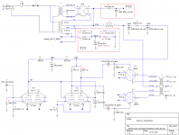
It's a bit confusing because the cathode circuit for the output tubes is drawn with the power supply heater section.
As I see it...
The cathodes (heaters) of the 2 output tubes are in parallel. There is a pair of 33R resistors in series across the heaters, to 'create' a single cathode point. This is connected to a 500R (2 x 1k in parallel- different W ratings? built on a Sunday night with what's in the parts box?) cathode resistor, bypassed with 220uF cap.
As for the 180R and 20uF.... are they really just 'hanging there' ? Beats me.
BTW, the ceramic power resistors from my regular supplier (justradios) with R>470 ohms are metal oxide, not wirewound. So a pair of 1K resistors would be non-inductive. Why the builder paired up a WW and ceramic (just looked at the auction pics) - deliberate or what parts he had?
Last edited:
I took the liberty to convert the schematic to a platform-independent format.
Nothing catches my eye as anything out of the ordinary. Except for the orphaned R1, C2 in the supply, but that could be an experiment. I don't have any experience with those specific tubes so I can't tell if the various values are reasonable or not. But they look 'normal'. I would have done things differently (added more sand in the biasing for example) but that'll always be the case.
~Tom
Attachments
Okay thanks. But if You didnt like how the amp sounded, where would you start modifying?I took the liberty to convert the schematic to a platform-independent format.
Nothing catches my eye as anything out of the ordinary. Except for the orphaned R1, C2 in the supply, but that could be an experiment. I don't have any experience with those specific tubes so I can't tell if the various values are reasonable or not. But they look 'normal'. I would have done things differently (added more sand in the biasing for example) but that'll always be the case.
~Tom
At first, we were talking about changin components for better components. But we decided that I should first make sure that the schematics of the amp is good, and then swap components.
If you guys confirm that the schematic look good, well I guess the reasons I'm not totally fond of the amp would be because of the components inside right? So I should start trying to figure out what can be upgraded?
I already bought the russian caps, I'll put them on. What else should I change?
Okay thanks. But if You didnt like how the amp sounded, where would you start modifying?
At first, we were talking about changin components for better components. But we decided that I should first make sure that the schematics of the amp is good, and then swap components.
If you guys confirm that the schematic look good, well I guess the reasons I'm not totally fond of the amp would be because of the components inside right? So I should start trying to figure out what can be upgraded?
I already bought the russian caps, I'll put them on. What else should I change?
I'd suggest giving Sheldon's post #18 a re-read....
First things first.
You've described what could be basic issues (buzzing and other noises). So, get a schematic (Or draw one up yourself. It will be good experience and it is DIY). Then measure all the voltages and calculate current across all components.
Next, track down any issues of hum or noise, until you have determined that it falls within expectations for the design.
Then, and only then, consider circuit or part changes. Otherwise it is random.
Sheldon
And, it may be that you just don't like the sound of DHT PP amps (or this particular circuit topology) with your speakers, even if it is working perfectly?
okay, I will do what sheldon told.
Be careful. I don't like messing with ordinary meter probes inside a live amp.
I use alligator clips, or (even better in most cases) hook-type grabber leads.
Figure out how to get the caps discharged safely before you start.
Clip to test points.
Hand out
Meter set to correct range (if necessary)
Power up
Record reading.
Power off (I usually power down via a power bar, so there is no AC inside the amp.
Discharge caps. (If you have a 2nd meter, leave it across B+ to meter the voltage.)
Move clip(s) to next test point.
It sounds tedious, but it beats getting a shock or melting the end of your test probe when it slips and you start welding inside your amp.

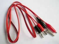
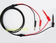
If you buy leads with banana plugs, it's a good idea to tape or heat shrink the exposed screw heads, since they are 'live'.
Attachments
I'm just wondering something. The two monoblocks do not have the same circuit, theirs seems to have some difference, yet no one mention it to me or told me what I need to rearrange...
Post the two schematics so we know what you are talking about, please.
That's really bad!!!
The preamp is an opamp design and the poweramp is tube push-pull!?
1. Other way around would be MUCH better: Tube pre & semicon power.
2. Opamp is worse than tube and discrete transistor design. Try to build a tube pre (not SRPP) or at least the "Bride of Zen" Nelson Pass pre with the IRF610 transis.
3. The wirewound resistors in your poweramp are crap. Change them to Mills.
4. The Jensen caps sounding lame and not very dynamic with deep stage but also narrower stage width, change them to Mundorf Supreme or DynamiCap.
5. The other cap C4 don't look good, change them to Epcos, Elna or Nichicon.
6. Change the output transformer & the choke to Lundahl & the house will rock!
7. Change the resistors to Takman metal (warm & open sound) or Takman carbon film (more warmth & body).
Last edited:
hi, well no I didnt bought the pre-amp, only the power amp.The preamp is an opamp design and the poweramp is tube push-pull!?
1. Other way around would be MUCH better: Tube pre & semicon power.
2. Opamp is worse than tube and discrete transistor design. Try to build a tube pre (not SRPP) or at least the "Bride of Zen" Nelson Pass pre with the IRF610 transis.
3. The wirewound resistors in your poweramp are crap. Change them to Mills.
4. The Jensen caps sounding lame and not very dynamic with deep stage but also narrower stage width, change them to Mundorf Supreme or DynamiCap.
5. The other cap C4 don't look good, change them to Epcos, Elna or Nichicon.
6. Change the output transformer & the choke to Lundahl & the house will rock!
7. Change the resistors to Takman metal (warm & open sound) or Takman carbon film (more warmth & body).
I'll change the jensen cap for the russian teflon ft-1.
I'll look for your other recommendation but I'm not sure if you are referring to the power amp or the pre-amp... Can you tell me which resistor needs to be change? and you wouldn't use the dynaco transformer on the power amp?? You would actually change them?
thanks
Last edited:
3. The wirewound resistors in your poweramp are crap. Change them to Mills.
Sorry, but I don't think the Mills can be true audiophile quality. They only cost 7x as much as good standard-quality, non-inductive resistors.
They do look nice.
it will take a couple of days.Murphy-
You are seeing two 'schools of thought' from the audio hobby playing here.
The 'circuit guys' and the 'component guys'.
BTW, how are those voltage measurements going?
thanks for your help.
btw, Which "school" seems to be more accpeted?
it will take a couple of days.
thanks for your help.
btw, Which "school" seems to be more accpeted?
The school that gives you the warm and fuzzy feeling on the inside! Simple as that.
Seriously though, I really really really cannot believe the microphonics and hiss are coming from the powersupply resistors!
The most interesting voltages for me would be on the anodes of the phase splitter, this wil tell if the differential amp is in balance at least.
BTW; I also found poor quality sound from an amp and falsely changed the first stage components but after no change to the sound.......nailed it down to the resistors used as current monitoring in the o/p stage cathodes. Calculating the size of component merely on the V*/R isn't enough. These weren't impulse rated and high peak currents can destroy film/ m/o types without showing any visible marks. Use ww types which are excellent.
richy
richy
Last edited:
so botht he components and design are important. As we pointed out, some resistor are clearly not meant for hifi, so I'll change those...BTW; I also found poor quality sound from an amp and falsely changed the first stage components but after no change to the sound.......nailed it down to the resistors used as current monitoring in the o/p stage cathodes. Calculating the size of component merely on the V*/R isn't enough. These weren't impulse rated and high peak currents can destroy film/ m/o types without showing any visible marks. Use ww types which are excellent.
richy
Last edited:
Sorry, but I don't think the Mills can be true audiophile quality. They only cost 7x as much as good standard-quality, non-inductive resistors.
They do look nice.
Mills sound warm & musical the normal wirewounds do sound restrained and harsh. I'm not delighted about the price of the Mills but the sound is too nice to ignore.

I refer to the poweramp. FT-I caps are not very dynamic and they do tend to sound lean & less colorful. Somehow the opposite of some Mundorf caps.
BTW, I'm not from the "component school", I design my own amps from scratch and I do repair jobs on McIntosh, Accuphase, Apogee etc.
BTW, I'm not from the "component school", I design my own amps from scratch and I do repair jobs on McIntosh, Accuphase, Apogee etc.
Use ww types which are excellent.
richy
3. The wirewound resistors in your poweramp are crap. Change them to Mills.
- Status
- This old topic is closed. If you want to reopen this topic, contact a moderator using the "Report Post" button.
- Home
- Amplifiers
- Tubes / Valves
- I think I made a mistake