More trial and error..
Well initial tests are interesting, I'm Running 410V across the rails. 205v app across each 6C33C. I am running mixed bias 42V on the top tube. the bottonm tube is adjustable to get a balance across the 150 Ohm cathode resistors. The PSU caps are balanced with 10K and 22K.
I am still running the MU sections with the FETs at the moment..I will look at how low I can get the cathode resistors and still have some sort of control. Idle current is set at approx 200mA. So I'm getting about 25V single heater and 30 Volt dual heater across the 150 Ohm Cathode resistors.
The supply is now not CT and floating..bass is still good! Some more tweeking to do..
I still have the Auto bias sound at the moment, however its a bit louder..Perhaps more open as well.
Its all Good fun.... The only problem is the stink off the power resistors as they burn in....or Out depends on your point of view....
Regards
M. Gregg
Well initial tests are interesting, I'm Running 410V across the rails. 205v app across each 6C33C. I am running mixed bias 42V on the top tube. the bottonm tube is adjustable to get a balance across the 150 Ohm cathode resistors. The PSU caps are balanced with 10K and 22K.
I am still running the MU sections with the FETs at the moment..I will look at how low I can get the cathode resistors and still have some sort of control. Idle current is set at approx 200mA. So I'm getting about 25V single heater and 30 Volt dual heater across the 150 Ohm Cathode resistors.
The supply is now not CT and floating..bass is still good! Some more tweeking to do..
I still have the Auto bias sound at the moment, however its a bit louder..Perhaps more open as well.
Its all Good fun..
.. The only problem is the stink off the power resistors as they burn in....or Out depends on your point of view....Regards
M. Gregg
I should add,
The choke psu is staying...
The bias was created with a voltage doubler giving about 100V from a 50V winding on the new higher voltage power Tx.
The top tube bias from the bottom tube power rail..
So the saga continues...
Nothing like playing for fun is there.. Oh well bed I suppose...more playing tomorrow....
Regards
M. Gregg
The choke psu is staying...
The bias was created with a voltage doubler giving about 100V from a 50V winding on the new higher voltage power Tx.
The top tube bias from the bottom tube power rail..
So the saga continues...
Nothing like playing for fun is there.. Oh well bed I suppose...more playing tomorrow..
..Regards
M. Gregg
Well,
Discussion in the background....
The 1st stage is still MU, 2nd stage is resistor anode, direct coupled to PI no grid stopper.
Combined with the mixed bias and increased main HT (410V) gives me switchable one and two heaters. Volume is way better. Using Ansar coupling between PI and 6C33c, Robert Hovland super cap between 1st MU stage and 2nd stage driver direct coupled to PI. Bass drive is good..
I think there is still room to reduce the cathode resistors and increase DC bias. Its run in time again and test (on full power at the moment you can't shout and be heard)(mozeners still in place) so the saga continues...
Hum is ear in the speaker low...sound stage is good.
It would be interesting to try some kind of direct drive with the 6c33c's.
Perhaps another project...
Something I found strange is it sounds better with the Goss band removed from the main power TX..wonder why<<perhaps its imagination...
The cork pads work well under the toroid for isolation...(just for interest).
Regards
M. Gregg
Discussion in the background....
The 1st stage is still MU, 2nd stage is resistor anode, direct coupled to PI no grid stopper.
Combined with the mixed bias and increased main HT (410V) gives me switchable one and two heaters. Volume is way better. Using Ansar coupling between PI and 6C33c, Robert Hovland super cap between 1st MU stage and 2nd stage driver direct coupled to PI. Bass drive is good..
I think there is still room to reduce the cathode resistors and increase DC bias. Its run in time again and test (on full power at the moment you can't shout and be heard)(mozeners still in place) so the saga continues...
Hum is ear in the speaker low...sound stage is good.
It would be interesting to try some kind of direct drive with the 6c33c's.
Perhaps another project...
Something I found strange is it sounds better with the Goss band removed from the main power TX..wonder why
<<perhaps its imagination...The cork pads work well under the toroid for isolation...(just for interest).
Regards
M. Gregg
I made OTL - 6AS7 /sorry, very ugly, but this is only try/according this schematic:Hi, would like to ask whether the vacuum tube OTL power amp worth to build? How is the sound performance if compare to normal output transformer type?? Does anyone has any good schematic diagram for OTL power amp, can share out, thinking to try to make one.
diytube.com :: View topic - OTL amplifier
Before phase splitter I put preampl. 1/2PCC88.
Current plate every 1/2 6AS7 - 70 ma. -Ubias about 90 V.
U under 820 + 820 ohm is 0 /no more 100 mV/, because currents upper and down shoulders in different direction
must be the sames, for avoid U under speakers. You can connect fast fuss 300-500 ma to save speakers and voltmeter. In the begin, after switching, there is some U, after few minutes U must be min. and You can connect speakers. There isn't cathode shunts for 6AS7 /like for 6S33S, I think that its sound is some sharp/ that will paint the sound, that is very important!
Sound is cool, awesome! The scene is very deep, bass is giant, details are unbelievable. /Now I can't listen my SE 300B, 2A3....with output transf., because every OT press Low Freq. and the scene, IMHO /.
Last edited:
Hi azazello,
I dont seem to be able to find the modified schematic of the preamp ecc88?
Did you put it after the volume control or before it?
Did you use any speaker protection? (on the psu or other)
and are you timing in the connection to the speakers? (after bias offset settles at start up).
Regards
M. Gregg
I dont seem to be able to find the modified schematic of the preamp ecc88?
Did you put it after the volume control or before it?
Did you use any speaker protection? (on the psu or other)
and are you timing in the connection to the speakers? (after bias offset settles at start up).
Regards
M. Gregg
For preamp. PCC88: +U = 270v, Rplate=20kohm, +Uplate=138v, Rcathode=390ohm, I plate=about 7 ma, Ucathode=2.7v., Rgride= about 500 kohm. Interstage cap about 470 nF. Potentiometer /about 2 - 10 kohm/ is in input.
My speakers are Fostex 206E - 8 ohm. 96 dB, for protection I use fast fuss in serial to speaker, depending how I can hear the level of the sound in my room. My speakers are with High sensitivity, volume is small and I use fuss 300 ma /with 100ma fuss is blowing/. I know that speakers never will die. For speakers with low sensitivity, fuss will be more, You will try.../I don't know how is the diameter of wire of Fostex 206E and how is max. current across the coil of speaker to decide what kind of fuss use/. For ex: If one from 4 triodes will die, U cathode res. will be 5-6 v, Current across 8 ohm will be about 700 ma, there are more wrong situations and wrong currents are different.
Waiting time to setting common current across common cathode resistor is about 3 min. After this I will connect speakers./Common current is +- about 100 mV. If all triodes are identical, U will be about zero/.
Last edited:
Holy thread revival, Batman!
I'm gathering the parts to make yet another Technics Futterman 6c33 OTL Amplifier. It will be all Russian tubes with cathode bias on the lower 6c33 and adjustable grid bias on the upper for that absolute minimum zero volts on the speaker outputs, regardless of how unmatched those tubes are.
Anyone care to comment on schematic? Especially about whether there is enough voltage swing from the phase inverter and if the PI's bias current is enough to drive a 6C33. Here's the designed load-line.
I'm gathering the parts to make yet another Technics Futterman 6c33 OTL Amplifier. It will be all Russian tubes with cathode bias on the lower 6c33 and adjustable grid bias on the upper for that absolute minimum zero volts on the speaker outputs, regardless of how unmatched those tubes are.
An externally hosted image should be here but it was not working when we last tested it.
Anyone care to comment on schematic? Especially about whether there is enough voltage swing from the phase inverter and if the PI's bias current is enough to drive a 6C33. Here's the designed load-line.
An externally hosted image should be here but it was not working when we last tested it.
I think that cathode biasing ain't no good idea for output valves in an OTL circuitry. These valves, in this configuration, necessarily will run in class AB with relatively (in comparison to the AC output current) low idle current. Driving the amp into significant output power simply will increase the negative bias voltage of the relevant valve too much.
*Imho* it is better to bias one valve by a fixed, but adjustible grid voltage, and to servo bias the other one in order to achieve symmetry.
Best regards, Uwe
*Imho* it is better to bias one valve by a fixed, but adjustible grid voltage, and to servo bias the other one in order to achieve symmetry.
Best regards, Uwe
Hi, As Kay Pirinha writes cathode bias doesn't work for an OTL except when it goes in class A, normally you run in AB to get useful power and then cathode biasing doesn't work.
In the OTL I originally designed I used 6C33C with 160V anode voltage and 200mA idle current which gives up to 25W in 8 ohm, 25W in 8ohm is 2.5A peak and the average DC current through the tubes are then 0.8A, (2.5/Pi) with cathode bias this is impossible as the bias point would shift with signal.
For this operating point grid voltage is normally around -45V, (it varies between samples of tubes) and the the driver need to give this voltage peak with low distortion. 250V on a split load phase inverter can not give this voltage and you need to run at least 400V or more.
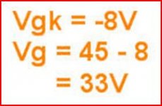
@Ketje: Wow.. don't know what happened that i had worse math capability than a kindergarten. Thanks for pointing that out! Vg should be 37 volts. Increasing the grid leak resistor from 330k to 390k would yield 39 volts on the P.I's grid. Close enough i think.
@Kay and tubetvr: Cathode bias doesn't work for full power in OTL? That is really a surprise.. This thread we're writing on is choke full with OTL schematics using cathode bias on BOTH upper and lower tubes (perhaps that's the key? cathode bias on both?). To my knowledge, at least three amps were built based on it (i read this thread from the beginning) and all owners claimed that they worked. Here's a separate thread of a working breadboard using autobias. Also, my schematic is based on A.Ciufolli's (supposedly) working design. He also uses cathode bias on lower tube and grid bias on upper. Perhaps these owners didn't crank the volume that high to notice any problem? I mean, 25W is actually a lot for an average sized listening room.
Pardon my noobness but i thought that's what cathode bypass capacitors are for? To bypass AC currents so that grid bias voltage remains constant? Would oversizing this bypass cap to 2200uF help?
Actually, i have a few questions if you don't mind helping me with. First, regarding PI's voltage swing, i can raise it to 500v. I'm using isolated switched mode PS so i can stack two to make 500v. I just want to know with my current schematic, what is the expected max output power? Again, the schematics that i roughly based mine on are all using only around 300-320v of B+ on the phase inverter so based on this, i suspect all owners didn't crank the volume high enough to notice any problem.
Also, i'm not comfortable seeing the 330K grid leak resistor on the phase inverter. I think i should terminate to the gain stage's ground, not to the feedback path as my schematic shows above. Does this matter?
An externally hosted image should be here but it was not working when we last tested it.
Ballpencil If you put a cathode bias you short AC circuit to Ground and you have nothing of signal for the lower rail. The cathodine shift has PER SE autobias but as you see, the cathode and anode resistors are in the same value, this kind of shift has not gain at all. Only serve like shift divisor.
@Kay and tubetvr: Cathode bias doesn't work for full power in OTL? That is really a surprise.. This thread we're writing on is choke full with OTL schematics using cathode bias on BOTH upper and lower tubes (perhaps that's the key? cathode bias on both?). To my knowledge, at least three amps were built based on it (i read this thread from the beginning) and all owners claimed that they worked. Here's a separate thread of a working breadboard using autobias. Also, my schematic is based on A.Ciufolli's (supposedly) working design. He also uses cathode bias on lower tube and grid bias on upper. Perhaps these owners didn't crank the volume that high to notice any problem? I mean, 25W is actually a lot for an average sized listening room.
As far as I recall, the cathode biased OTL that was being discussed extensively in the earlier part of this thread turned out to be very low power; just a couple of watts or so. That is not much compared with thre 25W that can be achieved using fixed bias.
Chris
Ballpencil If you put a cathode bias you short AC circuit to Ground and you have nothing of signal for the lower rail. The cathodine shift has PER SE autobias but as you see, the cathode and anode resistors are in the same value, this kind of shift has not gain at all. Only serve like shift divisor.
Not sure if i understand you but the cathode bypass capacitor is not on the cathodyne. It's on the lower 6C33.
Again, i am paralleling a 220uF bypass capacitor with the lower 6C33 cathode resistor, won't this bypass AC signals and keep the DC bias constant? At least this is what merlinb's book says.. and this book has been published many times. Here's the first chapter from the book which is available for free on his website (valvewizard.co.uk), discussing cathode bypass capacitor.
merlinb's first chapter said:Another way of looking at it is to say that the
capacitor decouples or bypasses to ground any AC signals on the cathode, so signal
current does not flow in the cathode resistor and the DC bias voltage remains
unchanged. With either explanation the result is the same; the cathode bypass
capacitor smoothes out changes in cathode voltage, helping to hold the cathode
voltage constant and thereby preventing cathode feedback.
Not sure if i understand you but the cathode bypass capacitor is not on the cathodyne. It's on the lower 6C33.
Again, i am paralleling a 220uF bypass capacitor with the lower 6C33 cathode resistor, won't this bypass AC signals and keep the DC bias constant? At least this is what merlinb's book says.. and this book has been published many times. Here's the first chapter from the book which is available for free on his website (valvewizard.co.uk), discussing cathode bypass capacitor.
I think that in this application, the size of bypass capacitor needed would be much greater than you are suggesting. (So large as to be unrealistic.) The problem, I think, is that it is not just a matter of bypassing the audio frequencies. Here is an attempt at an estimate:
As tubetvr pointed out, the average current through the tube increases from say 0.2A in the quiescent state to 0.8A when delivering 25W. If one is using cathode biasing, then in order to keep the DC cathode voltage approximately constant, the bypass capacitor would have to be carrying that additional 0.6A, without significant voltage change, for as long as the high power output is being demanded of the amplifier. Let's suppose the high power is required for 10 seconds in a loud passage in the music, and that we could tolerate a total cathode voltage change of 6V during that interval. That's 0.6V per second. The current through a capacitor is related to the rate of voltage change by the formula I=C dV/dt. So putting in the numbers, that implies the bypass capacitor would need to be 1 Farad. A bit unrealistic!
Chris
As cnpope says it is unrealistic to use a cap big enough to keep voltage over cathode resistor constant during any longer music passage so fixed bias is needed, an alternative could be to use a Zener diode instead of cathode resistor but it need to be a high power type.
I think there is a misunderstanding what is meant when saying that a cathode cap is keeping cathode potential constant, yes it can keep the potential constant over the signal envelope and that how it is working in a class A amplifier, e.g. an ordinary small signal stage with cathode bias, then the cathode resistor is bypassed so it will not give negative feedback and the cap value is chosen so that low enough frequencies are bypassed. This is also how it works in power amplifiers with cathode bias, in those the operating point is chosen so that current is almost constant at idle and full power, look at datasheet for EL34 or other tubes.
In a class AB or B stage where there is a big difference between idle and full power current it will not work and without the big difference in current you can't get any reasonable output power. To change operating point so that current will be constant doesn't work either as you will exceed max anode dissipation over a few W of output power.
The other alternative is mixed bias.
An adjustable fixed bias with limited amount of cathode bias. (Which I prefer)
The fixed bias is designed fail safe as much as possible, so should the wiper lose contact with the pot the tube is shut down.
A red plating 6C33C is interesting but a bit dangerous..I would not trust servo control, I though about it however the heat and electronics don't work well together.
Others may feel different..
I wanted to be able to leave the room with it playing and be confident that a tube would not meltdown.
The other thing to be aware of is the power that an OTL draws from the mains..don't underestimate it!
I run my OTL with half heaters and with half the power draw as a switchable option. Which also reduces heat in the room.
Regards,
M. Gregg
Last edited:
What is mixed bias?
Thanks a lot for the explanation. I learned something new.. In other words, cathode bypass cap would keep a constant bias voltage if it's allowed to swing same magnitude of positive and negative voltage; i.e class A (charging and discharging symetrically), correct?
As you may have guessed, i avoided using fixed bias on the lower tube because i have to make another power supply just for that bias voltage. The upper tube's bias is easy.. i can make divider from the -150v rail to get around -45v. The lower tube would need -195v with respect to ground.
Last edited:
- Status
- This old topic is closed. If you want to reopen this topic, contact a moderator using the "Report Post" button.
- Home
- Amplifiers
- Tubes / Valves
- Vacuum Tube OTL power amp!!