I run,
33 ohm with 4700uF 63V in the cathode.
If you use different types of bias top and bottom tube you can get some shift in the clipping.
So I use mixed in both tubes..and I fuse both of the supplies..+/-
Take care with the amount of stored energy in the supply its leathal..I touched a wire down after power off when testing the supply was dead and blew a hole through some aluminium. Discharge resistors are a must fit!
You lose power in the cathode resistors, so many prefer fixed bias only.. So its up to you really..I would not use different bias for each tube..
I tried fixed in one tube and cathode in the other it didn't sound very good!
I would also over spec the bias supply...(just my opinion) so you have more than you need..these tubes are very strange at times..
With mixed bias the value of the cathode resistor is less so the discharge time of the cathode cap is reduced. I tried it without the cap in place I prefer the warmer sound the cap gives to the mix..power is a little better as well. I ran with a mosfet and zener working as a power zener for a while across the cathode cap to clamp the voltage...but I just use mixed bias now.
Regards
M. Gregg
Last edited:
I guess I should mention,
I bias up my amp with both triodes (ON) for 200mA.
Then when I switch one heater off the bias drops (On its own no adjustment)..to just over half that. (mixed bias)
I can switch either heater on its own or put both on..this means that I can share the ware by running on one side of the tube for a month then switch over to the other side of the tube a month. Or I can have both on.
There is a BIG reduction in power draw and heat. (less power but you would be surprised it sounds more than half still available).
Regards
M. Gregg
![m60-signal[1].gif](/community/data/attachments/395/395412-d9480423368b77dda448d36c3212b035.jpg)
Since everybody is reminding about increasing the Phase Splitter's B+, i did some verifying if my design really doesn't have the swing needed to get maximum power output.
As mentioned by tubetvr, each output tube is fixed-biased at around -45v. This means each side of the cathodyne must swing at least 90Vpp with low distortion. Am i correct so far?
Here's my verification result.
As can be seen below, to my knowledge, there is actually enough swing since each side of the cathodyne can swing 100Vpp! Now i'm confused! Did i do something wrong? Or does everyone want to increase the B+ because that 100Vpp is actually too distorted? I have preemptively suspected the latter by green-highlighting the least linear area.
edit:
On a second thought, since Va is 160v and B+ is 250v, then the actual swing is 250-160 = 90V or 180Vpp.. This means each split load can swing 180:2 = 90Vpp.. Still enough swing! Help?
An externally hosted image should be here but it was not working when we last tested it.
Last edited:
ballpencil
B+ for split load phase splitter need to be around 400VDC to achieve good output swing .
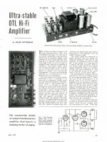
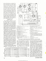
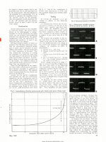
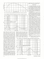
BTW , for your information read this attached old OTL article from J.Futterman , and if you have chance read AudioXpress magazine , issue from May 2014 , OTL article from Mr.F.Camorani & M.Pagogna .
( and yes , my personal opinion is that Circlotron OTL is much easy for DIY . )
Best Regards !
B+ for split load phase splitter need to be around 400VDC to achieve good output swing .
BTW , for your information read this attached old OTL article from J.Futterman , and if you have chance read AudioXpress magazine , issue from May 2014 , OTL article from Mr.F.Camorani & M.Pagogna .
( and yes , my personal opinion is that Circlotron OTL is much easy for DIY . )
Best Regards !
Attachments
-
 Electronics-World-1959-05-page-067.jpg657.3 KB · Views: 440
 -
 Electronics-World-1959-05-page-068.jpg819 KB · Views: 417
 -
 Electronics-World-1959-05-page-069.jpg658.4 KB · Views: 389
 -
 Electronics-World-1959-05-page-070.jpg718.3 KB · Views: 343
 -
 Electronics-World-1959-05-page-108.jpg947.9 KB · Views: 154
B+ for split load phase splitter need to be around 400VDC to achieve good output swing
Yes this is what everybody is saying but why? Again, i checked from the load line chart that there is actually enough swing from the phase splitter (90Vpp), unless i made a mistake somewhere.
Thanks a lot for that article. Reading it now..
( and yes , my personal opinion is that Circlotron OTL is much easy for DIY . )
I'm not a fan of circlotron since it can't use bipolar PS on the output tube AND higher output impedance than a Technics Futterman.
Just realized from reading the article that gain of a cathodyne is not the same as common cathode configuration.. In fact, it's closer to a cathode follower. So that's why B+ needs to be high.
Yes Cathodyne phase splitter have no voltage gain .
BTW , not sure but under termin ` common cathode configuration ` phase splitter did you mean actually on differencial phase splitter ? .
Edit : I can give you so much contra information why Circlotron OPS are better choice for OTL than any SEPP OPS , ( but I won`t right now
) .
Last edited:
Not on their website yet, but there will be an OTL tube amp review coming up at Stereophile -- it's in the current issue:
Tube Power Amp Reviews | Stereophile.com
Tube Power Amp Reviews | Stereophile.com
BTW , not sure but under termin ` common cathode configuration ` phase splitter did you mean actually on differencial phase splitter ? .
No, i mean common cathode gain stage vs cathodyne stage.
here's where i am so far..
nearly finished the front end. just waiting for some 2-watts resistors to finish the job (thanks to suggestions to raise the cathodyne's voltage).
6N2P gets regulated 6 volts from 7806 while 6N6P's heaters are connected in series for 12 volts coming from cheap ATX PSU.
Here's the all-important speaker protector for when the tubes decided to short-circuit. Didn't bother making this since it's only about USD 2 completed.
Just got the notification today that my 6C33s have just been shipped.. Hopefully it'll be here in 3-4 weeks.
@M.Gregg, any idea about the fixed bias voltage on your mixed bias setup?
nearly finished the front end. just waiting for some 2-watts resistors to finish the job (thanks to suggestions to raise the cathodyne's voltage).
An externally hosted image should be here but it was not working when we last tested it.
6N2P gets regulated 6 volts from 7806 while 6N6P's heaters are connected in series for 12 volts coming from cheap ATX PSU.
An externally hosted image should be here but it was not working when we last tested it.
Here's the all-important speaker protector for when the tubes decided to short-circuit. Didn't bother making this since it's only about USD 2 completed.
An externally hosted image should be here but it was not working when we last tested it.
Just got the notification today that my 6C33s have just been shipped.. Hopefully it'll be here in 3-4 weeks.
@M.Gregg, any idea about the fixed bias voltage on your mixed bias setup?
The bias supply is 50V AC voltage doubled so its about 100V ..maybe 110V. one for each leg..Remember this is mixed bias.
I run the 6C33C for 12 hours with just heaters before applying any B+
Set up is with about 6.3-6.6V across the 33 ohm cathode resistor..
So I start the amp with the tubes shut down and run up, then slowly set the bias on all tubes in stages at 1V wait 15mins--3V wait 10mins then 4V then 6.0V and let it run for half an hour then set the 6.3V (Both heaters running)
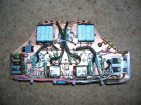
Why didn't you use plain PCB and solder tag strip to it, instead of perf board....you need to remember this is about current not just voltage.
EG. in the picture..
If your coupling caps fail you will red plate the 6C33C..what voltage rating are they?
Make sure you have a very thick earth to the speaker Gnd..
You need to think very carefully about the heat in this amp..
EG how hot is the regulator going to get?
And whats the voltage rating of the resistors you have used? Please be very careful...
Your safety is up to you..however please don't underestimate the heat and supply power.
Regards
M. Gregg
I run the 6C33C for 12 hours with just heaters before applying any B+
Set up is with about 6.3-6.6V across the 33 ohm cathode resistor..
So I start the amp with the tubes shut down and run up, then slowly set the bias on all tubes in stages at 1V wait 15mins--3V wait 10mins then 4V then 6.0V and let it run for half an hour then set the 6.3V (Both heaters running)
Why didn't you use plain PCB and solder tag strip to it, instead of perf board..
..you need to remember this is about current not just voltage.EG. in the picture..
If your coupling caps fail you will red plate the 6C33C..what voltage rating are they?
Make sure you have a very thick earth to the speaker Gnd..
You need to think very carefully about the heat in this amp..
EG how hot is the regulator going to get?
And whats the voltage rating of the resistors you have used? Please be very careful...
Your safety is up to you..however please don't underestimate the heat and supply power.
Regards
M. Gregg
Attachments
Last edited:
Something else to be considered is that your plate voltages will be different.
If the bottom tube is cathode biased, the B+ available will be the B+ value minus the voltage drop of the cathode resistor.
So your power supplies really should be different voltages so that you can have equal voltage drops across the tubes. Otherwise its pretty evident that the lower tubes will saturate first, nor will they be at the same operating point as the top tubes.
I don't see a good way to solve this problem as boosting the B+ available for the bottom tube would be a trick- you can't count on an exact value for the voltage drop across the cathode resistors.
So both top and bottom tubes have to be managed in a similar fashion...
And whats the voltage rating of the resistors you have used?
Basically, i work with what is available ubiquitously here in my country without resorting to ordering stuff from overseas too often. You can't even find solder tags easily here. I've used the same type of resistor on my Aikido preamp and they're holding up just fine. I understand your concerns about safety. I think there isn't any major current flowing on the section that i built on the perf board so it should be safe, no thick wires necessary here. LM7806 will only be dropping 6 volts at 350mA.. so with only 2 watts dissipated, it shouldn't be too hot.
First and second stage coupling caps are rated at 275V with the yellow ones being X2 caps. Cathodyne to Output stage caps will be at least 630V. The most critical i think is the coupling for the lower 6C33. The end going to the cathodyne will be at 300V while the end going to 6C33 will be about -195V (-150V + (-45V bias)) so there will be about 500V across this cap.
-45V bias? Yes, i've been thinking about the suggestions to ditch autobias on the output tubes so i ordered those high voltage LED power supplies. They're adjustable from 36 to 48V. The plan is to bias the upper tubes via voltage divider on the lower -150V rail while the lower tubes for each channel get its own adjustable bias voltage for zeroing the speaker outputs.
I am contemplating about building wether Alastairs or Tim Mellows OTL.
If I would go with Alastairs and would want to built separate mono-blocks for each channel could I
- use half the VA ratings for each transformer for each channel?
- use one 6J5 tube as U1?
Any other things I should be aware of?
What keeps me off a bit of Tim Mellows amp is that is was described as "too bright" by one builder. Any other experiences?
Thanks,
Heinz
I am contemplating about building wether Alastairs or Tim Mellows OTL.
If I would go with Alastairs and would want to built separate mono-blocks for each channel could I
- use half the VA ratings for each transformer for each channel?
- use one 6J5 tube as U1?
Any other things I should be aware of?
What keeps me off a bit of Tim Mellows amp is that is was described as "too bright" by one builder. Any other experiences?
Thanks,
Heinz
Do you have a link to the schematic of Alastair's OTL?
Concerning "too bright," I think that could have a variety of different interpretations. My own view would be that the "tube sound" that some people enthuse over is likely related to colourations introduced by the use of output transformers, etc., in a conventional tube amp. An OTL, by contrast, is more like a solid state amp in its sound, since it doesn't introduce those transformer-related colourations. In other words, the OTL (or an SS amp) gives a more precise and accurate rendition at its output of what is fed in at its input. This might be interpreted by some people as sounding "too bright" in contrast to a conventional tube amp.
Chris
- Status
- This old topic is closed. If you want to reopen this topic, contact a moderator using the "Report Post" button.
- Home
- Amplifiers
- Tubes / Valves
- Vacuum Tube OTL power amp!!