WRT point one above, in practice the 6AS7G has excellent high current capabilities as well. Simplicity of the driver demands some conversation; I use a driver that has one gain stage and then a simple cathode follower, which is able to drive multiple triode grids without distortion. So far I have yet to see a simpler amplifier based on pentodes of any sort.
Yes, and that is exactly what I meant by a simple driver. Using pentodes can, in some cases, make it even simpler if a single differential stage offers enough gain, or )oh the horror) one can go differential pentodes
") but in general, decoupling the gain stage by a follower is always a good idea as it almost completely prevents blocking, offers a bit of A2/AB2 drive, and makes it possible to use less and/or smaller coupling caps.
but in general, decoupling the gain stage by a follower is always a good idea as it almost completely prevents blocking, offers a bit of A2/AB2 drive, and makes it possible to use less and/or smaller coupling caps.I believe that your use of the circlotron topology is also the reason for simplicity of the driver - just compare with totem-pole drivers for fun.
2) if a 6C33 or 7241 is used, then independent bias settings are a good idea, done by also having independent driver circuits. At this point, if these tubes are used, then the driver is considerably more complex.
Exactly - there is really no other way but separate drivers (or at least followers) for each tube. Fortunately, one can gt away with less pairs of 6S33S (and similar) but we are still talking doubling or tripling at least one driver stage. With pentodes this complication is shifted to Vg2 regulators. One drawback may be it makes automatic bias much more complex, but you don't meddle with the actual audio signal. Again, as good engineers say, there are no solutions, just different compromises... this shift is however possible due to lower Cin of pentodes, more G1s can be strapped in parallel before a redesign of the actual driver is necessary. Still, for a sane number of tubes in parallel, this is no great issue - unless one is strictly limited in available tube types (as may be the case if one wants a series produced product).
3) and 4) are no different if 6AS7s are used, and
Hehe there is no Ig2 on triodes
(I was not referring to Ig1) and normally with pentodes this current does not contribute to the output current unless we have a circlotron. Not immediately obvious but in a pentode circlotron one gets floating Vg2 with respect to tube cathode (so independant of output voltage) by cross-connecting Vg2 to Vp of the oposite bank (if a higher Vg2 is needed, it must be pegged on top of the existing Vp as a power supply 'tap'), however, the Ig2 does not go through the load then. By using local regulators for Vgs, referenced to tube cathode, but supplying the regulator from the Vp of the actual bank in question (with extra voltage added if necessary) Ig2 gous out the cathode and through the load - and unlike totem-pole outputs, it does so completely symmetrically for both halves of the circuit. This trick can really only be used in a circlotron, and it reclaims Ig2 as a useful output current, which is actually the default behaviour of a triode - Ig2 is not 'lost'. Further, because a pentode OTL load line goes somewhat into the knee of the pentode characteristics, at this point the plate current falls and G2 current rises quite a lot so the G2 current contribution is not as small as one would think (usually 2-4% in BPTs well away from the knee). With proper Ig2 limiting (to limit G2 dissipation - no shortcuts here, G2 is tiny compared to the plate and has very low thermal inertia!), you get a good 10%, sometimes more, depending on actual tube. Simply put, this gives you 1 'virtual' extra tube for every 7-10 real ones, which is not bad at all, for just connecting the input to a Vg2 regulator differently.
4) is very similar with 6AS7 because mu of only 2 makes for negligible miller effect. Good current capability and this actually is the reason i mentioned that only 3 commonly available triodes are suitable for OTLs, 6S33S, 6S19P, 6AS7G.
5) we get the same short circuit tolerance with the 6AS7s. I have often done a short-circuit as a demonstration at shows by shorting out the amp and then running the preamp at full volume. In general OTLs seem to be tolerant of short circuits as long as there are no stability issues.
Exactly - because the difference in Vak with voltage on the load and no voltage on the load is relatively small, it's not that much more extra dissipation driving a short. With pentodes however that is something one has to consider in a design as minimum Vak can be as much as half that of an equivalent power triode design. Because of this one can be tempted to cut down on tubes - however, output impedance considerations usually prevail (*). Even so, a pentode has a definite maximum current for maximum drive (lets assume Vg1=0 for that) so it's really a current source, hence current is intrinsically limited. In cases as above, this can help with the design.
However - open circuit is a real problem for pentodes. Any amount of current driven into an open circuit clips the amp which means Vak goes down to nearly zero, at which point there is a huge current going through G2. Recycling G2 current helps immensely with that, because the regulator is referenced to the cathode, and this will go up to the plate power supply, the G2 regulator will run out of voltage and Vg2 will drop, ditto current, but as I said, this is only possible for a circlotron. No such problem with triodes - Vak falls, there is no current and there is no alternate path for it to flow like G2 in pentodes. With proper design taking care of dissipation a triode OTL is completely safe with all loads without any extra protection.
(*) unless one relies on a LOT of NFB. It should be stressed that rather large amounts of NFB are far less of a problem with OTLs because with an OTL it's fairly simple to obtain very high full power bandwidth open loop with simple circuits. Doing the same with transformer coupled amps is nearly impossible. Assuming care is taken with stability, NFB will be FAR less atrocious with an OTL, and if one is trying to optimize for efficiency (getting the most out of available tubes), may be a good way to get good performace without compromising too much. The less compromising way would be to desing a loudspeaker specifically with a given OTL in mind, counting on higher (but constant) output impedance
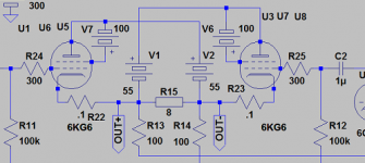
If you want to go low voltage Ua, don´t forget PL519 in enhanced triode mode(or whatever you want to call it), see example. Works well with something like Ua 60-70V and Ug 100V floating on top.
Yes - and this is a good example of passing Ig2 through the load, rather than having it lost, so it works like a triode. The circuit does present some challenges as to naming
- one could call it 100% UL too Full pentode would have a local regulator for each G2 referenced to the cathode of the same tube (regardless that the actual G2 current comes from the other cathode).
BTW there was a brief aside on G2 drive. A lot of swing is required, far more than the output signal - a couple 100 Vpp is not unusual. It's often dealt with by having a class B or C driver to prevent needlessly driving the G2 of the output tubes into hundreds of negative volts while the outer PP side gets full drive. G2 drive is also generally very linear, one could almost say too linear, thus best suited for class B amps, provided good control of the crossover region (biassing may be 'fiddly') - the crossover region is very small and needs to be fairly tightly controlled to avoid gm doubling-like effects (very similar to a BJT output amp).
Since we'd be passing a lot of current through the tubes, their net gain WRT Ug2 would be far below 1, so it's a rather 'bad' follower. Still, consider a build like in the pic above (except with drive to G2 and G1 at a fixed (slightly positive?) voltage - at zero output, the tubes are in the middle of the crossover area and there is no feedback to the drive voltage, so this still needs to be well controlled for bias and offset stability (note that some sweep tubes need quite a lot of time to stabilize and have quite big tolerances to begin with). However, at full swing, especially for tubes with low G2 voltages (and these would be preferred in such an application) there is considerable feedback as the cathode tries to follow Ug2. This mechanism does make the bias setting a bit more 'soft' and more manageable WRT a transformer coupled amp with G2 drive, but one still needs to provide hundreds of V, sourcing current, and at negligible distortion...
Last edited:
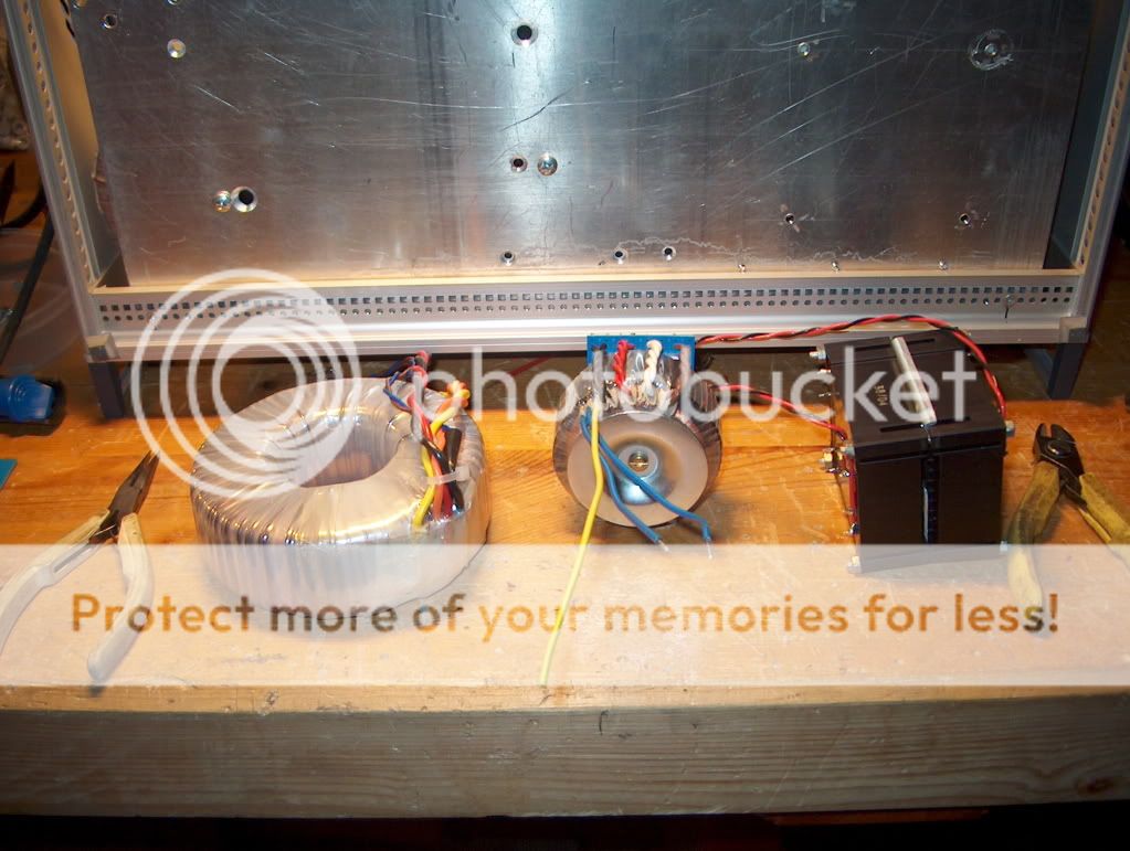
Here's a little trick if you are using toroids:
You can stack them if you have a longer bolt to hold on to them. It works best if one is on top and maybe the other two below. You may have to play with phasing of the AC mains so that the magnetic leakage is helpful rather than harmful to the transformer cores.
The other thing is to make sure you use a stainless non-magnetic bolt! A regular steel bolt represents a magnetic short of sorts to the toroid and will heat up a lot hotter than the transformer, no matter if the manufacturer of the transformer supplied a steel bolt, don't use it.
Thanks Mr Atma for this data. Never could imagine take in mind this.
This is a good contribution.


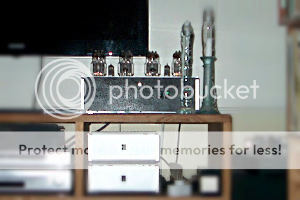
Cool! Any idea why the toroids are buzzing? Are you for example saturating the core every half cycle - if so some very small power resistors in series with windings might get you out of the woods by limiting the peak current to something more reasonable..
Mechanical buzzing - can you isolate the toroids on sorbothane mats or similar?
Mechanical buzzing - can you isolate the toroids on sorbothane mats or similar?
When you say 'DC trap' this was something on the mains side of the transformer? A set of diodes bypassed by electrolytics? If no, then you need to add this, if yes, noisy transformer.First i suspected DC from the mains since it sometimes is dead silent and some other times buzz loudly.
A DC-trap didn´t change the behavior.
So either a badly fabricated toroid or something i missed ??
Hm. I would try something more like 1000uf...
Why 1000uF ?
My experience is that nothing below 4700uF works good.
10mF is double that.
In the US, the u means 'micro' and quite often 'm' means micro too.Why 1000uF ?
My experience is that nothing below 4700uF works good.
10mF is double that.
You must mean 'mill' as in milli-farad'?
If that is true then you will simply have to replace the toroid(s) or find some way to isometrically isolate them from the chassis.
The amp is apart on the work table.
The toroid for 6C33C heaters is making a loud buzz.
First i took out the small PCB transformers i hooked up to the heater windings for the bias supply.
Most of the buzz gone ??
I´m not overloading the toroid, i checked my connection to the bias transformer everything in phase no mixed up windings etc.
What is going on, what did i miss ??
Or is it so simple that it can´t take the rated load and stay quiet.
New standalone bias toroid and new heater toroid is going to be hammered in during the evening.
The toroid for 6C33C heaters is making a loud buzz.
First i took out the small PCB transformers i hooked up to the heater windings for the bias supply.
Most of the buzz gone ??
I´m not overloading the toroid, i checked my connection to the bias transformer everything in phase no mixed up windings etc.
What is going on, what did i miss ??
Or is it so simple that it can´t take the rated load and stay quiet.
New standalone bias toroid and new heater toroid is going to be hammered in during the evening
.
Are you running the PCB transformers off of the secondary of the toroid? If they are presenting an uneven load to the toroid, that could cause the core to vibrate, even though it appears to be within spec.The amp is apart on the work table.
The toroid for 6C33C heaters is making a loud buzz.
First i took out the small PCB transformers i hooked up to the heater windings for the bias supply.
Most of the buzz gone ??
I´m not overloading the toroid, i checked my connection to the bias transformer everything in phase no mixed up windings etc.
What is going on, what did i miss ??
Or is it so simple that it can´t take the rated load and stay quiet.
- Status
- This old topic is closed. If you want to reopen this topic, contact a moderator using the "Report Post" button.
- Home
- Amplifiers
- Tubes / Valves
- Vacuum Tube OTL power amp!!