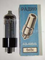
They seem to have very high plate current ratings- 1.4 Amps!
According to the Sylvania datasheet this also means peak current!
Best regards!
Hi
My experience with PL519 tube is that specified Philips data is valid but for only very short time of peak cathode current , of few milisecond duration , in real life tube PL519 will blown internal cathode to tube pin link easy and fast , that is actually the weak point of this tube , similar case is with tubes PL509 , EL519 and El509 , regardless to tube manufacture brand .
PL504 tube don`t suffer from this internal over current peak contact link failure , it is pretty rugged tube .
Best Regards for all !
Do you know to any good PL504 OTL schematics?
Regards
M. Gregg
Hi Mr.Gregg !
The best PL504 OTL Amp solution for everyday 24/7 use will be small amp with triode connected 4xPL504 per channel driving 4 x 8 ohm speaker = 32 ohm , or even little higher impedance , based on Atmasphere M60 topolology only !
For higher output power and lower speaker impedance just insert more PL504 tube in parallel .
Special want to point Atmasphere driver DC coupled circuit which is the best solution for full control over PL504 power tubes , but for best possible Amp sonic to .
Atmasphere input voltage gain stage is OK to , but there is only small place for modification and tweaking to .
Best Regards !
Last edited:
Thank's for the reply,
Where can I get a look at the M60 circuit?
What is the optimum number of pl504's for 16 Ohms or is 8ohm not viable?
I guess the DC coupling stops capacitor blocking?
Regards
M. Gregg
M.Gregg
Complete Atma-Sphere M60 DIY article with full DIY support from Mr.Ralph Karsten ( Atmasphere ) you can found here :http://www.diyaudio.com/forums/tubes-valves/161112-what-tubes-tube-amp-2.html
For 16 ohm speaker you need about 6 or 8 PL504 tubes .
Yes DC coupling driver avoid effect of blocking distortion , but permit A/A2 class of operation for output power tubes with superb sound performance.
BTW , universal good solution for optimum match to relative low output power OTL Amp is to connect 4 or more standard 8 ohm speaker in series , since today is possible to by very good quality speaker unit for relative low money , before 30 or 40 year ago that was not possible .
Best Regards !
Hi banat , or PL36 triode connected too
Yes !
BTW , I prove the excellent quality of PL36 tube on output RF power stage for AM Pirate transmitter , the PL36 stand 1KV B+ with no problem for years , PL504 up to 1,3KV , and PL519 up to 1,5 KV , but PL519 very often flash & burn the cathode to tube pin link , PL 36 & PL504 never .
Best Regards !
Last edited:
I never experimented with PL36 in RF power stage , but I use it in my Futterman OTL ( triode connected ) a long time ago, about 8 years without any problem it's really a good tube, and in the last 7 months in an Circlotron OTL triode connected too but with AC coupling driver , with 10 PL36 in each channel I have output impedance of 1.2Ω which is pretty good result .
Last edited:

Hmmm....
Interesting. Ive Never seen a PL509/19 with a failed cathode-connection link, and believe me, Ive overloaded severely many a PL509 over the years!....
Ones I'm using at the moment, Ive pretty well hammered many times and have now been used everyday for must be 6 months or more....
(Mozener, Triode-connected as described earlier in this thread)
Ive a couple of different make ones running, Two NOS ones and a couple of quite well used ones....
--Then again, I don't use 'em in RF Linears where flash-over/Arcs are more 'expected'!!
Nothing wrong with PL/EL509/19, and more linear than the small PL36 too....
Hi Alastair E !
Yes my observation ( and not only mine ) & experience was made driving PL519/EL519/PL509/EL509 tube on the edge of endurance , 1,7 Mhz , AM , RF class C with B+ up to 1,5 KV , or using this tubes for AF modulator (AF amplifier ), class B , with B+ of 800 V .
For example : driving PL519 with up to 1,5 KV on the plate only very small out of resonance point lead this tube to flash over of internal cathode to tube pin link .
After I destroyed this way bunch of PL519 I replace this TV tubes with suitable RF power tubes like GK71 or GU 13 and have no more problems.
Best Regards !
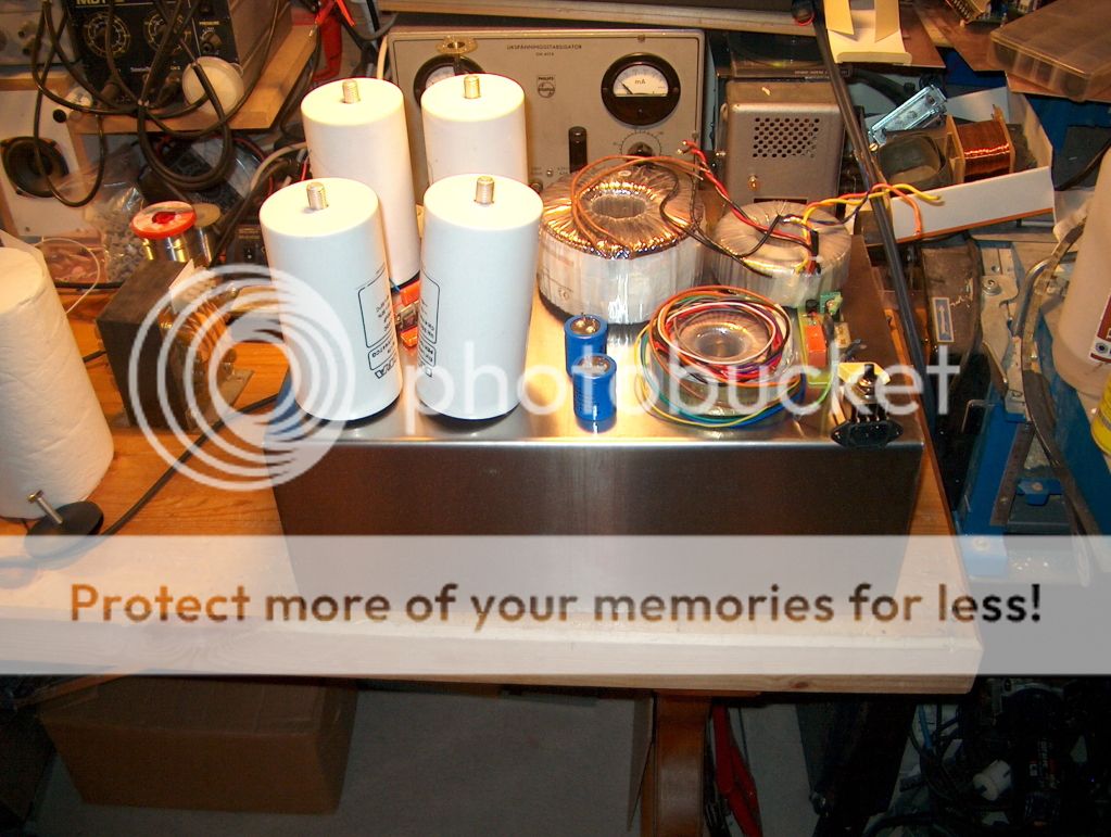
Here's a little trick if you are using toroids:Time for another try.
First one grew out of the box.
This time the PSU goes into a 19" 6H box.
If it won´t fit this time i´ll give up.
The RIFA caps is tight fit in this box so who nows
You can stack them if you have a longer bolt to hold on to them. It works best if one is on top and maybe the other two below. You may have to play with phasing of the AC mains so that the magnetic leakage is helpful rather than harmful to the transformer cores.
The other thing is to make sure you use a stainless non-magnetic bolt! A regular steel bolt represents a magnetic short of sorts to the toroid and will heat up a lot hotter than the transformer, no matter if the manufacturer of the transformer supplied a steel bolt, don't use it.
Last time i had to hammer it togetter with a large sledgehammer.
And it took about 2hr to disasemble enough for tweaking.
Not going to happen again.
I usually have some plastic washers isolating the bolt through the transformer but if a stainless does it better i´ll try that.
And it took about 2hr to disasemble enough for tweaking
.Not going to happen again
.I usually have some plastic washers isolating the bolt through the transformer but if a stainless does it better i´ll try that.
That´ll be hard to find here in the land of metric
Re. Pentode OTL
Actually, this would be confusing OLG output impedance with apparent CLG output impedance. While closed loop impedance does indeed fall, it does nothing about the intrinsic voltage drop in the device itself, as this is a physical property which no amount of gain trickery can change.
That being said, pentodes vs triodes in an OTL in fact illustrate that this is not majorly relevant to output impedance but rather maximum output power.
A pentode OTL can indeed be more powerful than the same OTL using the same pentodes connected as triodes, simply because the minimum voltage drop 'at the knee' of the pentode characteristic can be made FAR lower than in a triode connection - and the reson is that the voltage on G2 is independent from the voltage on the anode, and can be made higher - quite significantly so. In fact in this respect a PL504 is a rather drastic example - as a triode it's not at all well suited for an OTL WRT efficiency. When it comes to triodes, the number of suitable tubes that can still be bought at reasonable prices, drops to only3 - 6S33S, 6S19P (but you need lots), 6AS7G and soviet equivalents.
The ability to independently control Vg2 also makes it possible for a pentode to have lower output impedance than the same pentode connected as a triode. As with most pentode characteristic devices, it's output impedance appeoaches 1/gm, and since gm is highly (in theory, for a perfect pentode, ONLY) dependent on Vg2, we can play with that a lot.
Normally, in a triode OTL the bane of it's existance is the voltage necessary across A-K to get enough current flowing, due to Rp of the tiode (usually at Vgk=0, although A2 and AB2 drive is possible and improves things somewhat). THis leads to going way over the limits with instantaneous dissipation even though we might still be within limits for peak cathode current, and hence requires more parallel tubes to keep under control.
In a pentode OTL, assuming the load line keeps the operating point below or at most at the knee, you can get a lot of current with a low voltage drop by increasing Vg2, and with it you get increased gm. At some point you can get more than you can achieve with the same tube strapped as a triode simply because you may not run into the dissipation limit.
However, some architectures are more suitable for such an OTL than others.
Totem-pole outputs must have floating G2 supplies in order to be truly symmetrical, otherwise the top half Ig2 flows through the load, whereas the bottom half Ig2 flows to the negative supply (or ground if the whole thing is AC coupled to load). Although such designs mostly use beam power tubes rather than straight pentodes, so Ig2 is a relatively small fraction of the anode current, with many parallel tubes the difference can add up. If you go to A2 or AB2 operation, then it's a given. And, it's all worse if the load is such that the operating point gets into the knee of the pentode characteristic.
On the oposite end of the spectrum, the circlotron is the best possible architecture of a pentode OTL. Because it's actually intrinsically symmetrical Ig2 can be made to either never go through the load, or (more complex but desirable) always go through the load. If A2/AB2 operation is sued, Ig1 always goes through the load. However, with pentodes, the number of floating supplies doubles, although they stilla ctually come in floating pairs so do not need to be completely independent.
To summarise, an OTL using pentodes has the following advantages:
1) Tubes can produce high peak currents at low Vak so:
- less heat is produced
- more power can be had from the same number of tubes reliably
- higher bias (class A) is possible with less tubes as lower Vak keeps dissipation inside limits even at higher bias
- triode A2/AB2 performance can often be achieved without going positive on Vg1, i.e. staying within class A1/AB1. This results in a much simpler driver.
2) Tubes can be balanced by independently adjusting Vg2 for each tube, best done with independant Vg2 regulator (some silicon here...). This optimizes output power and distortion while still keeping the driver simple.
3) In a circlotron topology Ig2 can be recycled through the load for extra available current, increasing efficiency and output power with the same number of tubes.
4) Output tubes are operated as pentodes, so there is a small advantage regarding input capacitance of a tube. This can come in handy when driving lots of parallel tubes with a simple driver - as is the norm in an OTL.
5) With proper design, the amplifier can withstand a short circuited output indefinitely. This can be used as load protection which does not require the signal to be passed through relay contacts.
But - there are also dissadvantages, and they are all really about managing G2 dissipation:
1) Pentode OTL cannot function without a load, although the biassing requires at least a small default load to determine the center point of the output (i.e. ground). Operation would only be completely reliable with a fairly high amount of NFB. More on that below.
2) NFB may be required to get very low output impedance. Note I wrote MAY - this depends on ehat one wants to optimize the design for - it it's lowers possible loss, then fewer output tubes are required but this also results in higher output impedance.
3) Ig2 apsolutely requires special management. As with any pentode, if the load is removed from the plate, the current wants to flow through G2. This also happens if the load is lighter than a certain minimum, the result is that the operating point of the pentode is shifted below the knee, where current through plate falls, but current through G2 rises very abruptly. This is particularly important with tubes that have a top cap - if it is removed or loose, contact is lost, Vak becomes zero and a huge current will attempt to flow through G2. As an example, for a PL504, at a given Ug2, doing this will pass about half of the maximum plate peak current through G2, and this will be a quick and fiery death for the tube and possible the rest of the amplifier.
The solution is current limiting Ig2. If each G2 has it's own regulator (silicon) this is a fairly small addition which can make the amplifier unconditionally safe. There are a number of techniques which can be used to keep maximum G2 dissipation almost constant and within limits, and thus maximize the contribution of each tube in the amp. It should be mentioned, however, that doing this purely with tubes is completely impractical.
It should also be noted that having NFB does not guarantee the safety of the tubes if the load is removed from a particular tube (i.e. the disconnected top cap scenario), and may not (depending on the amount of NFB) guarantee the safety of the tubes avan if the load was removed from the output. For that, one needs a more comprehensive protection scheme, but that is really a good idea anyway.
If you run a lot of feedback, yes, but I think you will find something quite curious. If you add a lot of feedback, it will not increase the power available into lower impedances. This is why I believe that increasing negative feedback does not actually decrease the output impedance.
IOW the term 'output impedance' as it is used in amplifiers today does not refer to the actual output impedance of the amplifier- it refers to the servo gain combined with the actual output impedance. Its confusing! But this is why I say that triode operation is more advantageous, because if you run the amplifier open-loop (no feedback) then you get the truth of what the actual output impedance is.
Actually, this would be confusing OLG output impedance with apparent CLG output impedance. While closed loop impedance does indeed fall, it does nothing about the intrinsic voltage drop in the device itself, as this is a physical property which no amount of gain trickery can change.
That being said, pentodes vs triodes in an OTL in fact illustrate that this is not majorly relevant to output impedance but rather maximum output power.
A pentode OTL can indeed be more powerful than the same OTL using the same pentodes connected as triodes, simply because the minimum voltage drop 'at the knee' of the pentode characteristic can be made FAR lower than in a triode connection - and the reson is that the voltage on G2 is independent from the voltage on the anode, and can be made higher - quite significantly so. In fact in this respect a PL504 is a rather drastic example - as a triode it's not at all well suited for an OTL WRT efficiency. When it comes to triodes, the number of suitable tubes that can still be bought at reasonable prices, drops to only3 - 6S33S, 6S19P (but you need lots), 6AS7G and soviet equivalents.
The ability to independently control Vg2 also makes it possible for a pentode to have lower output impedance than the same pentode connected as a triode. As with most pentode characteristic devices, it's output impedance appeoaches 1/gm, and since gm is highly (in theory, for a perfect pentode, ONLY) dependent on Vg2, we can play with that a lot.
Normally, in a triode OTL the bane of it's existance is the voltage necessary across A-K to get enough current flowing, due to Rp of the tiode (usually at Vgk=0, although A2 and AB2 drive is possible and improves things somewhat). THis leads to going way over the limits with instantaneous dissipation even though we might still be within limits for peak cathode current, and hence requires more parallel tubes to keep under control.
In a pentode OTL, assuming the load line keeps the operating point below or at most at the knee, you can get a lot of current with a low voltage drop by increasing Vg2, and with it you get increased gm. At some point you can get more than you can achieve with the same tube strapped as a triode simply because you may not run into the dissipation limit.
However, some architectures are more suitable for such an OTL than others.
Totem-pole outputs must have floating G2 supplies in order to be truly symmetrical, otherwise the top half Ig2 flows through the load, whereas the bottom half Ig2 flows to the negative supply (or ground if the whole thing is AC coupled to load). Although such designs mostly use beam power tubes rather than straight pentodes, so Ig2 is a relatively small fraction of the anode current, with many parallel tubes the difference can add up. If you go to A2 or AB2 operation, then it's a given. And, it's all worse if the load is such that the operating point gets into the knee of the pentode characteristic.
On the oposite end of the spectrum, the circlotron is the best possible architecture of a pentode OTL. Because it's actually intrinsically symmetrical Ig2 can be made to either never go through the load, or (more complex but desirable) always go through the load. If A2/AB2 operation is sued, Ig1 always goes through the load. However, with pentodes, the number of floating supplies doubles, although they stilla ctually come in floating pairs so do not need to be completely independent.
To summarise, an OTL using pentodes has the following advantages:
1) Tubes can produce high peak currents at low Vak so:
- less heat is produced
- more power can be had from the same number of tubes reliably
- higher bias (class A) is possible with less tubes as lower Vak keeps dissipation inside limits even at higher bias
- triode A2/AB2 performance can often be achieved without going positive on Vg1, i.e. staying within class A1/AB1. This results in a much simpler driver.
2) Tubes can be balanced by independently adjusting Vg2 for each tube, best done with independant Vg2 regulator (some silicon here...). This optimizes output power and distortion while still keeping the driver simple.
3) In a circlotron topology Ig2 can be recycled through the load for extra available current, increasing efficiency and output power with the same number of tubes.
4) Output tubes are operated as pentodes, so there is a small advantage regarding input capacitance of a tube. This can come in handy when driving lots of parallel tubes with a simple driver - as is the norm in an OTL.
5) With proper design, the amplifier can withstand a short circuited output indefinitely. This can be used as load protection which does not require the signal to be passed through relay contacts.
But - there are also dissadvantages, and they are all really about managing G2 dissipation:
1) Pentode OTL cannot function without a load, although the biassing requires at least a small default load to determine the center point of the output (i.e. ground). Operation would only be completely reliable with a fairly high amount of NFB. More on that below.
2) NFB may be required to get very low output impedance. Note I wrote MAY - this depends on ehat one wants to optimize the design for - it it's lowers possible loss, then fewer output tubes are required but this also results in higher output impedance.
3) Ig2 apsolutely requires special management. As with any pentode, if the load is removed from the plate, the current wants to flow through G2. This also happens if the load is lighter than a certain minimum, the result is that the operating point of the pentode is shifted below the knee, where current through plate falls, but current through G2 rises very abruptly. This is particularly important with tubes that have a top cap - if it is removed or loose, contact is lost, Vak becomes zero and a huge current will attempt to flow through G2. As an example, for a PL504, at a given Ug2, doing this will pass about half of the maximum plate peak current through G2, and this will be a quick and fiery death for the tube and possible the rest of the amplifier.
The solution is current limiting Ig2. If each G2 has it's own regulator (silicon) this is a fairly small addition which can make the amplifier unconditionally safe. There are a number of techniques which can be used to keep maximum G2 dissipation almost constant and within limits, and thus maximize the contribution of each tube in the amp. It should be mentioned, however, that doing this purely with tubes is completely impractical.
It should also be noted that having NFB does not guarantee the safety of the tubes if the load is removed from a particular tube (i.e. the disconnected top cap scenario), and may not (depending on the amount of NFB) guarantee the safety of the tubes avan if the load was removed from the output. For that, one needs a more comprehensive protection scheme, but that is really a good idea anyway.
WRT point one above, in practice the 6AS7G has excellent high current capabilities as well. Simplicity of the driver demands some conversation; I use a driver that has one gain stage and then a simple cathode follower, which is able to drive multiple triode grids without distortion. So far I have yet to see a simpler amplifier based on pentodes of any sort.Re. Pentode OTL
To summarise, an OTL using pentodes has the following advantages:
1) Tubes can produce high peak currents at low Vak so:
- less heat is produced
- more power can be had from the same number of tubes reliably
- higher bias (class A) is possible with less tubes as lower Vak keeps dissipation inside limits even at higher bias
- triode A2/AB2 performance can often be achieved without going positive on Vg1, i.e. staying within class A1/AB1. This results in a much simpler driver.
2) Tubes can be balanced by independently adjusting Vg2 for each tube, best done with independant Vg2 regulator (some silicon here...). This optimizes output power and distortion while still keeping the driver simple.
3) In a circlotron topology Ig2 can be recycled through the load for extra available current, increasing efficiency and output power with the same number of tubes.
4) Output tubes are operated as pentodes, so there is a small advantage regarding input capacitance of a tube. This can come in handy when driving lots of parallel tubes with a simple driver - as is the norm in an OTL.
5) With proper design, the amplifier can withstand a short circuited output indefinitely. This can be used as load protection which does not require the signal to be passed through relay contacts.
2) if a 6C33 or 7241 is used, then independent bias settings are a good idea, done by also having independent driver circuits. At this point, if these tubes are used, then the driver is considerably more complex.
3) and 4) are no different if 6AS7s are used, and
5) we get the same short circuit tolerance with the 6AS7s. I have often done a short-circuit as a demonstration at shows by shorting out the amp and then running the preamp at full volume. In general OTLs seem to be tolerant of short circuits as long as there are no stability issues.
- Status
- This old topic is closed. If you want to reopen this topic, contact a moderator using the "Report Post" button.
- Home
- Amplifiers
- Tubes / Valves
- Vacuum Tube OTL power amp!!