I find Alastair's design fascinating and I am wondering whether one could do likewise using say triode connected EL509, 6LQ6 or similar. Thoughts? I know that such tubes are traditionally run pentode mode in Futterman style amps but why could on not use triode mode to simplify things?
I find Alastair's design fascinating and I am wondering whether one could do likewise using say triode connected EL509, 6LQ6 or similar. Thoughts? I know that such tubes are traditionally run pentode mode in Futterman style amps but why could on not use triode mode to simplify things?
Well--Yes, I dont see why not....
When I first thought about an OTL years ago, I looked at the 'Sweep-Tube OTL by Allen Kimmel, a Very complicated Circlotron machine....
That one used EL/PL509, and I bought a pile of them in readyness as they were cheap then.
I however, moved over to the 6C33c as it seemed a 'better' choice, and the PL509 remained cold....
Kimmel used a sort of dual drive in his design, Grid 1 driven sorta 'normally' and the Screens driven by MOSFET follower from a 250V supply, from signal on the grid.....
I would think the Autobias idea would work with either layout, std. grid drive or 'super triode-mode', as Kimmel called his idea....
The PL509 I'm thinking would give around half the O/P power per tube in comparison to the 6C33, so you would have to double up on them....
Ive drawn up and tested a more normal input stage with two gain-stages before the splitter, with F.B. into Cathode, I'll put it up later....
--Using a 6SN7 in first/second stages so no need to modify chassis. Only 5 extra parts used.....
Apart from the extra gain, there's no apparent glaring difference in quality...
")
Ive drawn up and tested a more normal input stage with two gain-stages before the splitter, with F.B. into Cathode, I'll put it up later....
--Using a 6SN7 in first/second stages so no need to modify chassis. Only 5 extra parts used.....
Apart from the extra gain, there's no apparent glaring difference in quality...
So no more FB problems?
Sounds good
Regards
M. Gregg
You're sharp tonight!--Well spotted!
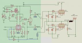
12AU7 was used in the schematic as I havent a 6SN7 'part' in the library, and didnt update its reference....
6SN7 used in real-life though, just check its pinout when you come to wire it up--Not the same as a 12AU7!....
R12/13 are just potential divider, so long as they are equal in this version, no probs, as we are wanting approx half +B for the MOSFET Bias to the first half of 6SN7.
The previous input stage had this voltage at approx 1/3 of +B, to set bias on phase-splitter--That now comes from the second 6SN7 common-cathode stage feeding it.
C5 can be anything around 1-22uF, its not a critical part, just additional smoothing for the MOSFET Bias--You could add a film cap across it too if you like.
--This same MOSFET reference voltage is used for both channels.
Q1, IRF710 has lower Gate-Capacitance than the IRF830, but in the simulations Ive done, it makes very little difference. The breadboard still uses the IRF830 as I havent got the IRF710 yet. Open loop bandwidth is well over 100KHz anyway.
--Works happily with the IRF830, so if you have those, they'll work fine.
C3 and C4, Should be 0.47 or 470N. The 'default' on my Proteus schematic capture is 220N, My error for not correcting...
12AU7 was used in the schematic as I havent a 6SN7 'part' in the library, and didnt update its reference....
6SN7 used in real-life though, just check its pinout when you come to wire it up--Not the same as a 12AU7!....
C3 and C4, Should be 0.47 or 470N. The 'default' on my Proteus schematic capture is 220N, ...
Alastair,
Your help is very much appreciated...I think it's great that you have overcome the feedback issue.
Just me checking that I use the correct parts!
Regards
M. Gregg
Last edited:
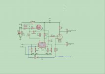
Ah--OK here we go....
No 470K in the FB loop. Its joined directly, so that the 18K on bottom end of phase-splitter sits on the O/P line....
C2 is 0.22 or 220N I'm using and works well....
If you wanted to pull up the LF pole, you could reduce its value to 0.1 or even 0.047....
No 470K in the FB loop. Its joined directly, so that the 18K on bottom end of phase-splitter sits on the O/P line....
C2 is 0.22 or 220N I'm using and works well....
If you wanted to pull up the LF pole, you could reduce its value to 0.1 or even 0.047....
 <<<< always takes a while!
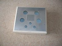
Yup--Dont see why not....
Ive run the same scheme at 100V, and 100 ohm, get around 160-180 through
the tubes, depending on whether Ive got 6C33, 6C41C or single heater 6C33C rigged up....
At 100V we get around 5-8 W depending on what tube/dual/single heater, into 8ohm
At 120V and 100ohm, you'll prob be puling about 200-220mA through each 6C33C tube (Both heaters) with around 100V across the actual tube itself....
Just make sure that you burn the tube heaters for a good couple of hours first-(Pref a day or so), then you can plug 'em into the amp, with dummy load across speaker-term --10 ohm WW will do--and run the amp for around 3 hours before trying to match up the valves, and shooting some sound through.
--This above, applies obviously only to New, Unused 'green' valves that have never been used....
-If you have some with some time under their belts, just fire 'em up and check the DC Offset....
Matching the valves for min DC Offset--
There's NO need to buy 'matched' valves--Which are difficult to find in 6C33 and always drift a little anyway.
You can measure the DC Offset across the 10 ohm WW and switch round the 6C33c until you get below 100mV offset.--(Best Ive ever achieved, was 15mV with a couple of pretty old 6C33, running single-cathode operation.)
--Normally this is pretty easy, you're sure to find a combo of tubes that give you below 100mV for both channels, if you have say, 6 tubes, just chop/change 'em round and test the offset....
You can quite happily pull the valves while the amp is still on and switch them round for the offset matching process, but I wouldnt recommend doing this if its attached to a speaker--Although thats the way I actually do it....
--Take Care, Oven-Glove time, they get HOT!
Even though 6C33C take 20 mins to stabilise, the 'offset test' can be checked as soon as the valves have fully hot cathodes, They seem to 'track' reasonably well over time in hours and time as in weeks, it varies very little, as they seem to age together.
Alastair,
Couple of questions:
How many watts are you dissipating in R9/R10?
What voltage do you have across them?
The reason I ask is Mills resistors seem to be 12 Watt and you are using 17W. (I did not want to parallel if not required).
I know you have used standard WW. I just like Mills Resistors.
Regards
M. Gregg
Couple of questions:
How many watts are you dissipating in R9/R10?
What voltage do you have across them?
The reason I ask is Mills resistors seem to be 12 Watt and you are using 17W. (I did not want to parallel if not required).
I know you have used standard WW.
I just like Mills Resistors.Regards
M. Gregg
Well, you're looking at around 200mA and 20V at 120V supply, so be in the order of 4W....
Your P-diss will be somewhat higher, being a higher value 150 Ohm and 150V supply, but will prob be in the order of 6-8W...
A 12W resistor will be fine, Not sure of the Mills construction--I'm going to look them up now....
I used 17W as those are what I had around, They get hot--but not excessively so...
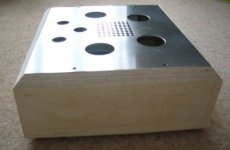
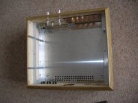
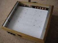
More slow progress.. work is getting in the way..LOL
I can start the internal build now the chassis is strong enough.
I will add more vent holes as I build, so it's still pulling the air from the front and around the top via the tubes and cathode resistors.
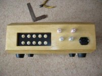
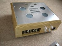
Inputs mounted! Lots to do.
Regards
M. Gregg
I can start the internal build now the chassis is strong enough.
I will add more vent holes as I build, so it's still pulling the air from the front and around the top via the tubes and cathode resistors.
Inputs mounted! Lots to do.
Regards
M. Gregg
Attachments
- Status
- This old topic is closed. If you want to reopen this topic, contact a moderator using the "Report Post" button.
- Home
- Amplifiers
- Tubes / Valves
- Vacuum Tube OTL power amp!!