Well, Rp is where the signal is produced for the MOSFET to follow...
Yes, 3 non-linear capacitances are bootstrapped by linear one, and it looks like a non-linear capacitive voltage divider.
About perfectly logical... it is funny to read how sometimes copyrighted science - looking articles are based on silly rules of thumbs. And all this is not about developing of large signals on high enough resistors, it is about loading of tubes on higher dynamic resistance in order to minimize their distortions.
Edit: this article reminds me colorful speeches of Michael Gorbachev... He has the talent, to speak a lot, say obvious things, but go figure what he meant in his speech actually...
")
Last edited:
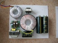
Yes, Ive used a polyprop there, as well as some very old small hermetically sealed ITT PIO caps rescued from some bit of military hardware...
I must admit,
I will build with standard components first!
I will only use an expensive component if I feel it is going to gain something. I have used silver from the jewelry suppliers (because it's cheap) and thought it worked well with PTFE sleeve. Some will argue that its not 99.9 % silver, however the difference is very small. I always use PTFE silver plated cable, It's cheap and carries more current with a smaller cross section. Some say skin effect is not the case with this, however if the silver is plated on the outside of the cable then the cross section cannot be reduced..current capacity is higher for the same cross section so if its not traveling in the silver how does it work? LOL
Anyway back to the topic.
Something I have been thinking about, you mentioned that the size of the cables on the heaters to remove the heat.
I guess solid copper may work well. Perhaps Antex no lead solder on the base with a higher melting point and cardas for the rest!
Regards
M. Gregg
Last edited:
Yes, Ive used a polyprop there, as well as some very old small hermetically sealed ITT PIO caps rescued from some bit of military hardware...
The main coupling-caps to the 6C33c are Russian 630V 0.47 K40y-9
Does the K40y-9 contain PCB?
I know the FT-3 is a good teflon capacitor.
Regards
M. Gregg
Last edited:
After a quick search I guess I can answer myself ...Yes PCB.
Had some issues with this linked to HV switch gear and caps in the past.
Interesting substance...goes under the guise of Oil. <<its not oil.
Very ...Very ...Very stable.....almost impossible to destroy.
High creep rate...i.e. spreads across an area over a period of time.
This creates the ability to penetrate the skin.<<makes it hard to wash off.
Where it finds its way to the liver and kidneys.
Your body cannot break it down so there it sits<<how long probably the rest of your life.
Repeated contact..liver and kidney failure.+ all the other goodies.
Sealed in a metal container because plastic breaks down.
Sorry off topic..
Regards
M. Gregg
The K40Y-9 I have are hermetically sealed things, there's a glass to metal ring soldered to the main case, and the lead again sealed to the glass....
Hoping/guessing they will be fine--So long as you dont cut 'em open, or they explode through mis-use!
FT-3 are good caps, only drawback is they are HUGE for the values!
As to connecting up the socket-pins, definately use a HMP solder to, as Thick a lead as you can manage, Multi-strand is easier to work with and conducts heat pretty good.
--Especially important for the heater-pins....
I went to a local motor-rewinders and got some heavy rubber-covered stranded cable and used that....
Thank's for the info.
The rule of thumb was if the component contains PCB its OK if it has no leaks. Only trouble is if it leaks it will contaminate the unit.
Just noticed some people cutting them open to see whats inside
I suppose a point would be if anyone sells equipment with this they may be liable. Suppose it depends on the country etc.
Anyway I will look at the stranded cable, gotta get that twist..lol
Still collecting parts..sooo slowwww. LOL
Regards
M. Gregg
Something's been bothering me since it was mentioned earlier in this thread....
And, That was the subject of the Gate-Stopper resistor and its effect on frequency/gain response.
I did some simulations of the gain-stage and phase-splitter, No feedback loop and, sure enough there is an effect on the freq. response.
The reason I'm not hearing this is of course, the global FB loop is 'covering up' this effect somewhat....
But There's another Huge fly in the Frequency-response, and thats of course, Mr Miller....
That 33K in series with the signal to G1 of the gain-stage, coupled with the Miller-Capacitance, has Much more detrimental effect on Open Loop bandwidth than the Gate-Stopper!
This is the drawback of using just one gain-stage with an amp of this type. The F.B. must be applied to G1 rather than the Cathode, as we have no OPT that we could 'wire-up backwards' to get the phase right to feed into Cathode.
Tim Mellow's sechematic follows the same form of F.B. 'format' feeding into the G1 of the first gain-stage, so I'm guessing his scheme must have a similar issue.
There is however, a reasonably simple option, although its not the perfect choice.
Replace the 33K with a more usual 270 Ohm grid-stopper, and the Vol. pot (47K) effectively becomes the high source impedance the F.B signal is working 'against', instead of the pot plus the 33K
--This however, causes the F.B Ratio to Alter depending on the position of the Vol. pot....
Alternatively, Delete the Global F.B. loop completely, but this will affect the amps' O/P Impedance and could affect damping....
(This was as I originally made the amp, after I went to a single gain-stage, It was only later I followed the Tim-Mellow idea of using a series resistor to the G1 of many K in value)
--The alternative of course, is to add a gain stage, and feed its cathode, something I was trying to get away from for simplicity....
With both resistors in the simulation now set to 270 ohm, the Open-loop bandwidth is now 5Hz to 85kHz -3dB
Changing these resistors in the real-life amp does appear to increase the H.F. response just slightly, changing the 33K had this effect, the original 100K gate-stopper appeared to have little/no effect on perceived sound....
I probably didn't notice the 'lack of H.F. due to the Global-F.B. as well as my speakers being a little 'top' heavy anyway....
Alastair,
What effect do you get if you use the 270 ohm grid stopper + feedback and put a 0.1 uF cap in series with the wiper of the volume pot? (No 33K)
Possibly make the 1Meg a variable and put the feedback 470K to the wiper (adjustable)
When you refer to the "two" resistors set to 270 ohm...I guess this is the gate stopper and grid stopper!
Still keeping the 470K feedback?
Regards
M. Gregg
Last edited:
Well, Adding a cap there wouldn't make a Huge difference,--depends on its value as to the LF pole....
--It wouldnt 'Isolate' the FB loop from the vol-pot if thats what was on your mind!
Yes--sorry, should have said, Both the G1 resistor and the Gate-Stopper are now 270 ohm 1/4W carbon-compo....
--Yes, still 470K global FB resistor....
--It wouldnt 'Isolate' the FB loop from the vol-pot if thats what was on your mind!
Yes--sorry, should have said, Both the G1 resistor and the Gate-Stopper are now 270 ohm 1/4W carbon-compo....
--Yes, still 470K global FB resistor....
Well--Yup, That should do it!....Hmmm--Not!
--But, wont the source impedance be reflected into the load (FB loop/G1 cct)...?
So, as the source imp changes with the pot setting, so would the O/P impedance of the Tx....
Plus, all the possible other issues with a Tx....
The addition of a gain stage--even a very low gain one, will allow the F.B into Cathode, and completely 'cure' the issues.
--But, That adds to the 'complication'! I dunno--compromises, compromises!
Last edited:
Nah--all valid ideas....sorta!
Ive been looking at the Tim-Mellow scheme which uses the same highish value series-resistor, and a Triode as the first device. It must also suffer the same effect, but that amp seems to please those that build it.
It also has the drawback of not compensating for the 20% drive differental between top tube and bottom,--just relying on the Gnfb to sort it out, instead of going with the Futterman 'scheme'....
Guess a Pentode as the first tube is a valid option,--gives Mr Miller a rest,--combined with a Pentode's distortions!
Maybe I'll experiment at some point, although as is, its sounding very nice anyway...
Well you have a strapped 6SL7 so unstrap it!
Regards
M. Gregg
Yup, and go back to a 6SN7 as the first and second tube, which I had with standard resistive loaded common-cathode-stages....
When I dropped this and went to a SL7 and MOSFET on top, Its sound improved, although gain was a bit lower...
Maybe a combo of MOSFET on top of first stage and a standard resistive loaded second stage would be worth trying....
Or, a low gain triode of some description for first stage and use SN7 for second ad phase-splitter....
But, Thats getting complicated in comparison to what we have now....
- Status
- This old topic is closed. If you want to reopen this topic, contact a moderator using the "Report Post" button.
- Home
- Amplifiers
- Tubes / Valves
- Vacuum Tube OTL power amp!!