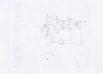
Also, what's the scoop on the screen taps connected to the feedback loop?
This was something Dynaco did to compensate for the imbalance in the primary of the output transformer.
voltage map
input tube 6SL7
pin 1) 0
pin 2) 142vdc
pin 3) 1.262
pin 4) 0
pin 5) 142
pin 6) 1.244
pin 7 h
pin 8 h
6SN7
pin 1) 141vdc
pin 2) 194
pin 3) 141
pin 4) 141
pin 5) 194
pin 6) 141
pin 7) h
pin 8) h
power supply voltage feeding the 100k plate resistor (6sl7) is 277vdc
voltage feeding the 22K plate resistor on the 6sn7 is 331vdc
You've only got 50V or so across the 6SN7. Not good. Get the B+ higher.
Morgan Jones reported that when he separated the supplies for the input voltage amp and split load inverter, he had some instability, so watch out for that. I might consider upping the B+, using it in common for the two stages, and increasing the 6SL7 plate resistor.
As you have it drawn, the feedback is quite low- this may or may not be what you want, but you should be aware of that.
Just finish making some changes
Changed the input tubes 6SL7's plate resistors from 100K to 200K
Upped the power supply voltages from 331vdc to 387 and 277 to 342
Voltage map
6SL7
Pin 1) 0
pin 2) 115
pin 3) 1.24
pin 4) 0
pin 5) 117
pin 6) 1.23
pin7&8 heater
6SN7 voltages
pin 1) 115
pin 2) 267
pin 3) 120
pin 4) 117
pin 5) 265
pin 6) 122
pin 7&8 heater
Sounds a lot better now. Do I need more plate voltage on the 6SN7's?
Do you have suggestions for feedback?
This is my second try and designing a driver circuit.
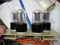
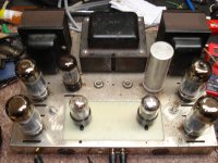
Picture of my 6SL7/6SN7 driver board.
Picture of my 6SL7/6SL7 driver board.
The 6sl7/6sl7 has a 6sl7 input with a 6sl7 long tail. While it sounded very good I will make a change to the plate resistors on the input tube and see how it sounds.
Changed the input tubes 6SL7's plate resistors from 100K to 200K
Upped the power supply voltages from 331vdc to 387 and 277 to 342
Voltage map
6SL7
Pin 1) 0
pin 2) 115
pin 3) 1.24
pin 4) 0
pin 5) 117
pin 6) 1.23
pin7&8 heater
6SN7 voltages
pin 1) 115
pin 2) 267
pin 3) 120
pin 4) 117
pin 5) 265
pin 6) 122
pin 7&8 heater
Sounds a lot better now. Do I need more plate voltage on the 6SN7's?
Do you have suggestions for feedback?
This is my second try and designing a driver circuit.
Picture of my 6SL7/6SN7 driver board.
Picture of my 6SL7/6SL7 driver board.
The 6sl7/6sl7 has a 6sl7 input with a 6sl7 long tail. While it sounded very good I will make a change to the plate resistors on the input tube and see how it sounds.
Attachments
Last edited:
With that B+, you should be able to squeeze out a few more watts. Look at the clipping at max power- is it symmetrical?
If you're happy with the sound, don't screw with the feedback. If you want to drop the source impedance and distortion, you'll want to get more gain in the driver. All of the gain before the output tubes is in the first stage (that's why Dynaco used a pentode). You can get slightly more by bypassing the cathode bias resistor (not the 100R) or swapping it for an IR LED. At the same time, you can put a CCS as the plate load. This will get the gain of the first stage up to 70 or so. That will translate to roughly 6dB of feedback, which is quite low. If you're feeling adventurous, you could convert the first stage to a cascode with a FET on the bottom- that will give you a boatload of gain. If you use a FET like a 2N5459 and that 200k plate resistor, the gain of the first stage will be 200 or so, giving you about 15dB of feedback. That's a more reasonable number.
If you're happy with the sound, don't screw with the feedback. If you want to drop the source impedance and distortion, you'll want to get more gain in the driver. All of the gain before the output tubes is in the first stage (that's why Dynaco used a pentode). You can get slightly more by bypassing the cathode bias resistor (not the 100R) or swapping it for an IR LED. At the same time, you can put a CCS as the plate load. This will get the gain of the first stage up to 70 or so. That will translate to roughly 6dB of feedback, which is quite low. If you're feeling adventurous, you could convert the first stage to a cascode with a FET on the bottom- that will give you a boatload of gain. If you use a FET like a 2N5459 and that 200k plate resistor, the gain of the first stage will be 200 or so, giving you about 15dB of feedback. That's a more reasonable number.
Idle current 50ma-ish?I'm only getting about 25 watts a channel out of it but it sounds really good.
No power supply mods yet running stock other than the 6n3cE output tubes and the individual tube bias.
Totally missed the 6n3c-e's (6P3S-E).
 I have a quad in my Joly 302b.
jeff
They sound good I like them better than EL34's
Same here. They sound great triode strapped also.
")
jeff
quote:At the same time, you can put a CCS as the plate load.
I still have the CCS boards that I got 4yrs or so ago and never used them. Can I use a HV PNP CCS board? If I can now to find the documentation on them.
Checked my semi pile and came up with some 2N5462's Can't remember why I bought 100 of them.
I still have the CCS boards that I got 4yrs or so ago and never used them. Can I use a HV PNP CCS board? If I can now to find the documentation on them.
Checked my semi pile and came up with some 2N5462's Can't remember why I bought 100 of them.
Hmmm.....
Thats not all That different from the front end of my breadboard OTL since I re-arranged it all....
Strapped SL7 with MOSFET on top, DC coupled to 6J5 Concertina Phase-splitter--Not Unlike the O/P schematic...
One thing to remember, a split-load phase-splitter 'likes' approx 1/3 of the voltage split across each device-- ie, for a +B of 300, that would be 100 across plate res, 100v across the valve and 100V across the cathode-resistor.
My 6J5 has 16K plate/cathode resistors and supplied by 340V. I get a more or less 1/3 split across each device....
To achieve this if DC coupling, the previous stage plate (Or MOSFET) needs to be at just around 100V, coupled to the Grid of phase-split with a 470K
(470K is to avoid distortion when nearing clipping of the phase-splitter,--serves no other purpose--Stops that Blatting noise if you really do something silly with the attenuator!)
--Easily done to set voltage with MOSFET on top, set the bias voltage for that device to approx 120, and the plate-load to around 10K, and cathode-res. 2.2K The O/P from MOSFET will be around 110V.....
--Works for me with 340V +B supplying both stages....
- Status
- This old topic is closed. If you want to reopen this topic, contact a moderator using the "Report Post" button.
- Home
- Amplifiers
- Tubes / Valves
- 6sl7 6sl7 dynaco driver board