A friend has purchased a pair of these monoblocks and has asked if he can fit KT88 in place of the existing 6550 (4 on each monoblock for 110W output)
Can anyone provide a schematic or any knowledge of if it is cathode biased / fixed biased etc.
Any info gratefully received.
Thanks,
Ian
Can anyone provide a schematic or any knowledge of if it is cathode biased / fixed biased etc.
Any info gratefully received.
Thanks,
Ian
I have two of the 110 Watt stereo amps (YM-100) with four 6650s and a 6AN8 per channel. These amps are based on one of the circuits in the Dynaco transformer catalog and are fixed bias. When I first got these I contacted the manufacturer here in California and asked for some info but didn't get very far. First I was told they are NOT fixed bias but I knew different. All other info I have found says their amps are cathode bias. Maybe mine are early ones as there are no serial numbers in the serial number block on the back. Anyway all you need to do is remove the bottom and check the size of the resistor on pins 1 and 8 of the output tubes. Mine are 10 Ohms which definitely means fixed bias, cathode bias would be 500 Ohms give or take. I think KT88s would be fine here. The circuit is very simple and it would be no problem to draw a schematic which I would love to see, hint, hint.
Craig
Craig
Bring out your dead (thread).
These monoblocks arrived at my door yesterday - one is blown. A quick look inside shows one of four 6550 has part melted screen resistor and another tube has completely "fried" screen and cathode resistors.
Anyone have schematics? Just being lazy -I will trace it if no response. The quick look inside showed 6AN8 front end (pentode voltage amp to direct coupled concertina splitter), 4 off Svetlana 6550C Output tubes which were originally cathode biased but has been converted to fixed bias at some point in the past, very neat job so maybe done at the factory.
Cheers,
Ian
Craig,
Done - That helps - Output tranny wires color codes are the same as the A451 and circuit is VERY similar to the 120W schematic. Will complete the trace and post - may not get to it for a while, 40 degrees C (104 degrees F) today and next 5 days are forecast at over 37 degrees C or higher so my workshop out the back of the house may not be a good place to be.
Cheers,
Ian
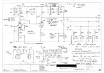
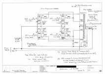
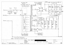
OK I promised the LS9100 schematic trace - here it is, I delayed posting until I had one monoblock fired up so that I could put typical voltages on it.
Cheers,
Ian
Cheers,
Ian
Attachments

Guys,
More info. The unit I traced above has been modified.
Mod #1 - Power Supply beefed up considerably, of all the electrolytic capacitors shown hanging off the rectifier, ONLY C8 to C15 shown on sheet 1 are original. All those "extras" shown on Sheet 3 have been added.
Mod #2 - The single output tube bias control has been replace with individual controls for each tube. Original looked like the Dynaco 120W circuit from here:
http://www.the-planet.org/dynaco/Misc/Transformers.pdf
This mod is poorly done in that the 100K adjustment pots are too high a value and very fiddly to try to adjust. 20K pots with the bottom fixed resistors adjusted accordingly (to say 82K) would be much better.
On ething which "pushed one of my buttons" was that the amp which had blown up had a 2.5 Amp fuse fitted in place of the normal 1 Amp which shows that the last guy to work on them was seriously "dodgy". He then had the cheek to put "Professionally Serviced by ***** " stickers on the rear panels. That is not what I wouild call professional.
Cheers,
Ian
Last edited:
Well they are finally both back together. New set of Output tubes for the blown up unit. Due to the grid leak resistor values (270K) I biased them very conservatively at 60mA idle each tube.
Both 6AN8A had weak triode sections (the concertina phase splitter) so put new RCA 6AN8A in both monoblocks.
Ran them for 2 hours on my system for a final confidence test.
What did I think of them ? Well frankly I far prefer my 10W per Channel 6V6 Baby Huey. Better Imaging, better pace, less low end "covered" veil, better top end extension, well better everything except maximum volume.
Cheers,
Ian
- Status
- This old topic is closed. If you want to reopen this topic, contact a moderator using the "Report Post" button.
- Home
- Amplifiers
- Tubes / Valves
- Aronov LS9100 - any info ???