Attachments
how about UL PSE or PP output stage, with ccs cathode, or leds
may be worth to have a sneak peek on this one http://www.dhtrob.com/projecten/el84_6bw6_pp_4.shtml
may be worth to have a sneak peek on this one http://www.dhtrob.com/projecten/el84_6bw6_pp_4.shtml
So how does it sound?
Any improvements to the circuit to recommend?
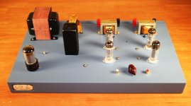
Clear and transparent, open sounding.
I've used for the driver tube
100R 2W triode strapping resistor
270R 5W cathode resistor bypassed with 100uf 50v cap
8K 10W anode load resistor
300 volts B2 voltage
The basic premise of this circuit is false. A particular valve has a particular 'sound' at a particular point in a particular circuit carrying a particular signal at a particular bias point. Using the same valve twice does not mean that you get more of that sound.
In this case the input EL84 is used in triode mode at one bias, while the output is run as a pentode with a different bias. The signal in the first valve will be much smaller than in the second valve.
In addition, the circuit has some shortcomings. The first stage has a grid stopper, but not the second stage where it is more likely to be useful. The first stage relies on the volume pot wiper staying in contact with the track. Better to have a coupling capacitor and a grid leak resistor. Finally, as other have said, the feedback goes to a decoupled point so will have no effect except possibly to create infrasonic instability.
The website is full of fine sounding words, but a poor design based on a misunderstanding.
Seems like you're in a bad mood DF.
Where does the guy get unreasonable with "fine sounding words". He just sensibly offers the concept, advises researching the origin and then states:
"I'm not looking for anything quite so exotic - I'd be happy with a clean 3-5 watts per channel from a fairly straightforward and simple circuit that utilizes commonly available and widely manufactured valves."
Your fixes to the circuit are noted but minor are they not? When I build this I'll try it your way. BTW the feedback doesn't go anywhere because none is implemented in the final design.
As far as the EL84 sound not adding together I'll bet it's a lot closer than using different tubes. Besides the EL84 is not too shabby as a driver and output tube so why not?
What you seem to be missing from the original article and this thread is the fun factor.
Lighten up brother...
Last edited:
Any thoughts?
Sorry, I must have misunderstood your questions!Any improvements to the circuit to recommend?
Hi!
For what it's worth:
I took the idea from the very same webpage, but trying (on the simulator) the driver tube in pentode mode
The reason why, is that from more sources it has been said that, this kind of feedback arrangement, is better implemented using a pentode driver..
I'm still learning about all this stuff, so...
FFT at 1W out looks good (I think), but I'm not sure if the simulation conditions are correctly set for a meaningful FFT plot...
Regards
J.
Attachments
You are running the second EL84 at 20W of continuous anode dissipation. You might want to turn that down to 12W at the most, and start measuring your screen grid currents as well.Hi!
For what it's worth:
Most tubes gets more linear as you turn the currents up, but they need to survive in the real world as well.
- Frank.
- Status
- This old topic is closed. If you want to reopen this topic, contact a moderator using the "Report Post" button.
- Home
- Amplifiers
- Tubes / Valves
- EL84 driving EL84 SEP