Like I mentioned the schemaic with 6n23p SRPP, try this. With 4mA sound is very thin, romantic but very very clean.Direct coupling is an idea I should research - never done that. Thanks!!
If you raise the current to 14mA - the bass gets more powerful, but the overall sound is less clean. From this something like 6-10mA current should be interesting.
The disadvantage is the need for cathode large resistor and capacitor. BUT DHTRob had idea of using a gas voltage regulator here! It will maintain the same voltage of say 105V without fluctating when the current is changing, just like with resistor and cap. So the sound with regulator can be more dynamic.
Just replace the 3K5 and 20uf PIO bypass with the regulator, but Ive never tried this.
I hope yu can read the schematic.
An externally hosted image should be here but it was not working when we last tested it.
Direct coupling is an idea I should research - never done that. Thanks!!
Yes. You could use that NP choke with the highish DCR and the additional series resistance will help decouple the capacitance of the winding.
HK
Last edited:
Can you please describe more your circuit? It is drawn differently but is this monkey/free lunch topology? Thanks.Yes. You could use that NP choke with the highish DCR and the additional series resistance will help decouple the capacitance of the winding.
The CCS fed shunt cap supply ensures any variation/drift is moved to the plate of the output tube.
HK
Can you please describe more your circuit? It is drawn differently but is this monkey/free lunch topology? Thanks.
MikyK: I like your circuit..
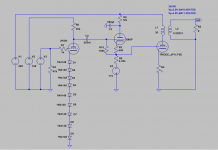
Describe.. hmm in words?.. okay, I can try: CCS filter supply sets fixed voltage drop across plate load choke and series resistor. So the plate voltage of the input tube sets up where it wants to and the CCS absorbs the tube to tube voltage variation (voltage drop across the CCS), the bias voltage of the output tube remains constant regardless of tube change at the input stage, because the filament return to grid is referenced across that constant voltage drop.
The series resistor adds to the plate load impedance, which is helpful at low frequencies, and also decouples the capacitance of the plate choke winding, which is helpful at high frequencies. 1k5 is one of the plate chokes that Andy had, which I why I drew it in. Something like ISO RC 160 plate choke 40H/30mA and 430R DCR would be good here.
Its just a stacked supply circuit, the only unique feature that I can find is the CCS fed shunt cap setting the bias for the OP tube. Circuit becomes simpler, power supply complexity increases somewhat, but well worth the trade off vs buying NC-20 interstage.
All sorts if cool jigsaw puzzles, if you could get away without the step up and go 1:1, something like: some interesting dc circuits – lab jc just because you can..
Last edited:
Thanks much. Understand I good that you will need two power supplies?MikyK: I like your circuit..
Describe.. hmm in words?.. okay, I can try: CCS filter supply sets fixed voltage drop across plate load choke and series resistor. So the plate voltage of the input tube sets up where it wants to and the CCS absorbs the tube to tube voltage variation (voltage drop across the CCS), the bias voltage of the output tube remains constant regardless of tube change at the input stage, because the filament return to grid is referenced across that constant voltage drop.
The series resistor adds to the plate load impedance, which is helpful at low frequencies, and also decouples the capacitance of the plate choke winding, which is helpful at high frequencies. 1k5 is one of the plate chokes that Andy had, which I why I drew it in. Something like ISO RC 160 plate choke 40H/30mA and 430R DCR would be good here.
Its just a stacked supply circuit, the only unique feature that I can find is the CCS fed shunt cap setting the bias for the OP tube. Circuit becomes simpler, power supply complexity increases somewhat, but well worth the trade off vs buying NC-20 interstage.
All sorts if cool jigsaw puzzles, if you could get away without the step up and go 1:1, something like: some interesting dc circuits – lab jc just because you can..
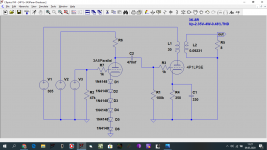
Okay. I have built again my circuit with 6N23P SRPP driving one 4P1L DC coupled. and in two words - Im amazed!
The details are pouring from the speakers. There is air around the instruments and everything is very clear. The music has emotions. This is BEAUTIFUL amp, I must say the BEST that Ive ever made!
Not much bass energy as I wrote before, probably due to only 4-5mA through the 6N23P.
I think with some modifications this can be even better.
I can try raising the B+ voltage and allowing more voltage (and current) for both tubes. The 4P1L is dissipating only around 7 watts.
Best regards, Michal.
It is post #1281Do you have a schematic Michal?
Driver operating current mainly affects A2 behaviour.Not much bass energy as I wrote before, probably due to only 4-5mA through the 6N23P.
There are no free lunch.
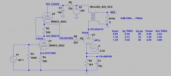
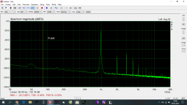
If you use such low value cathode capacitor, the LF -3dB bandwith will be rising, in this case even close to 25Hz.
Try -at least- an order of magnitude larger capacitor (100-330uF) and LF -3dB point go down even to 4Hz.
The capacitor value depends of OPT parameters, in the 100-330uF range greater or lesser hump would be possible in the 5-20Hz region. The hump moves down and die down, as you increase the capacitance.
Attachments
Driver operating current mainly affects A2 behaviour.
There are no free lunch.
If you use such low value cathode capacitor, the LF -3dB bandwith will be rising, in this case even close to 25Hz.
Try -at least- an order of magnitude larger capacitor (100-330uF) and LF -3dB point go down even to 4Hz.
The capacitor value depends of OPT parameters, in the 100-330uF range greater or lesser hump would be possible in the 5-20Hz region. The hump moves down and die down, as you increase the capacitance.
Hmm, thank you for simulating my circuit
 now I have 39uF eectrolytic as a bypass, but I have some 330uF philips so I can try...
Now I was experimenting with the cathode caps. I pu there a 390uF nichicon elco, then a 10uF MKV again and I could not tell any difference. But the bass are not right still, I think the problem must be in another place than bypass cap. Probably the big cathode resistor?
I also tried the Ultrapath, with the 10uF MKV, again, no difference. So I sticked with the traditional cathode bypassing.
I also tried the Ultrapath, with the 10uF MKV, again, no difference. So I sticked with the traditional cathode bypassing.
Edit: To be accurate, I think it doesnt lack bass, but what it lacks is bass control.Now I was experimenting with the cathode caps. I pu there a 390uF nichicon elco, then a 10uF MKV again and I could not tell any difference. But the bass are not right still, I think the problem must be in another place than bypass cap. Probably the big cathode resistor?
I also tried the Ultrapath, with the 10uF MKV, again, no difference. So I sticked with the traditional cathode bypassing.
If you don't use cathode /resistor/ blocking capacitor, the limiting factor of power is the resistor value AND the OPT's inductance.Probably the big cathode resistor?
The "5k" OPT at 20Hz must be at least 40H.
If it lesser, the power bandwidth bottom frequency (when the OPT impedance close to appropriate) is rising (5000=2*pi*f*L).
Are you looked the -for example- 5W output at 20, 30, 40, 50Hz with oscilloscope?
If the OPT impedance is not correct at actual frequency, the side of sine is dented.
Suppose, that OPT's inductance is 40H or greater.
If you have cathode blocking capacitor, the cathode complex impedance is R paralleled Zc.
If you use enough large capacitor, which has low impedance at low frequencies, it's dominates in the cathode complex impedance.
10uF (ideal capacitor) at 20Hz about 796R, and cathode resistor is 2500R. Z about 604R at 20Hz.
300uF at 20Hz about 26.5R. Z about 26.2R at 20Hz so value of R is negligible.
Hmm, it is funny. There is very likely difference between 10uf and 300uf cap, but I think the output transformer cant pass it so I can not hear itIf you don't use cathode /resistor/ blocking capacitor, the limiting factor of power is the resistor value AND the OPT's inductance.
The "5k" OPT at 20Hz must be at least 40H.
If it lesser, the power bandwidth bottom frequency (when the OPT impedance close to appropriate) is rising (5000=2*pi*f*L).
Are you looked the -for example- 5W output at 20, 30, 40, 50Hz with oscilloscope?
If the OPT impedance is not correct at actual frequency, the side of sine is dented.
Suppose, that OPT's inductance is 40H or greater.
If you have cathode blocking capacitor, the cathode complex impedance is R paralleled Zc.
If you use enough large capacitor, which has low impedance at low frequencies, it's dominates in the cathode complex impedance.
10uF (ideal capacitor) at 20Hz about 796R, and cathode resistor is 2500R. Z about 604R at 20Hz.
300uF at 20Hz about 26.5R. Z about 26.2R at 20Hz so value of R is negligible.
I use a tranny that was designed for pentodes, not for triodes. DCR is 250 ohms, inductance probably 16H ( this told me a friend which sold they to me). They were running in circuit with only 25ma through them. This is the current they were designed for.I have tried 6P15P triode connected with these OPTs, voltage 300 volts, current only 20ma. They were deep bass but TOTALLY lacking control. Hmm, it is a 5k transformer and my tube had a 15kohm resistance....
Yes, I thought it will be this problem. He told me that they are okay for about 45hz, so he was pretty accurate...16H transformer, 5k ... at 49.7Hz!
At 20Hz it's only 2k, so impedance matching there not optimal.
Trioded 4P1L Ri about 1k6.
Can you help me with one think? In datasheets, it is written for example that the trioded 4p1l has Rp of 1.6kohms So 5k is useable.
But when I will calculate the actual resistance of the tube, for example with 200 volts on the anode and 40mA through it it will have resistance of 5000 ohms. What value is important, the written by the datasheet, or the actual in the circuit? Thank you very much.
Khmmmm....200 volts on the anode and 40mA through it it will have resistance of 5000 ohms.
It's not Ri.
Tube's internal resistance is dUp/dIp at constant Ug.
Delta plate voltage and delta plate current is small values.
Some years ago Ale Moglia measured 4P1L
4П1Л/4P1L triode curves – Bartola(R) Valves
4П1Л/4P1L triode curves 2 – Bartola(R) Valves
The suggested Ri (1k1) IMHO is a bit low, later -if I remember correctly- he calculated with 1k6.
Some years ago I measured my -proto- CCS loaded 4P1L preamp output impedance (with brute force method).
It was about 1k5 -a little lower- so without CCS -few MOhm- impedance this is near to tube's Ri.
- Home
- Amplifiers
- Tubes / Valves
- One more 4P1L SE