You mean something like this?
Yes, except that you wouldn’t need the 0.2 uF cap between IT and 300B grid.
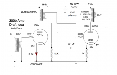
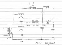
Like this? I have a pair of LL1660/18mA. More current would be better of course.
Yes, that’s it. I think you could try the LL1660/18mA's at a somewhat higher current than 18 mA since you won’t be using anything like their maximum output voltage capability. Somewhere between 20 and 25 mA would probably be fine.
the 0.1uf betwen the 300B cathode will introduce some feedback , or i'm wrong ? i know it is usual on old WE design but together with negative feedback or ultrapath capacitor . i never seen it alone ?
It is shown alone in RDH 4. I have also seen it like this in schematics from the 1930-ies.
It is shown alone in RDH 4. I have also seen it like this in schematics from the 1930-ies.
there are hundreds of amplifier schemas in these old books that doesn't mean they're all good. I have myself tried this "bootstrap capacitor" in conjunction with several configuation, ultrapath or traditional cathode bypass. and I always at the end preferred a simple 200uf polypro on the cathode. at the time a 100uf polypro would have cost the price of a car so they had to find alternative solutions.
")
the 0.1uf betwen the 300B cathode will introduce some feedback , or i'm wrong ? i know it is usual on old WE design but together with negative feedback or ultrapath capacitor . i never seen it alone ?
According to RDH 4 a negligible portion of the signal voltage will occur across the capacitor at all signal frequencies if its reactance is small at the lowest frequencies to be amplified. So, not much feedback.
there are hundreds of amplifier schemas in these old books that doesn't mean they're all good. I have myself tried this "bootstrap capacitor" in conjunction with several configuation, ultrapath or traditional cathode bypass. and I always at the end preferred a simple 200uf polypro on the cathode. at the time a 100uf polypro would have cost the price of a car so they had to find alternative solutions.
So, you have tried this capacitor in several configurations, but not the one discussed here?
the 0.1uf betwen the 300B cathode will introduce some feedback , or i'm wrong ? i know it is usual on old WE design but together with negative feedback or ultrapath capacitor . i never seen it alone ?
According to RDH 4 a negligible portion of the signal voltage will occur across the capacitor at all signal frequencies if its reactance is small at the lowest frequencies to be amplified. So, not much feedback.
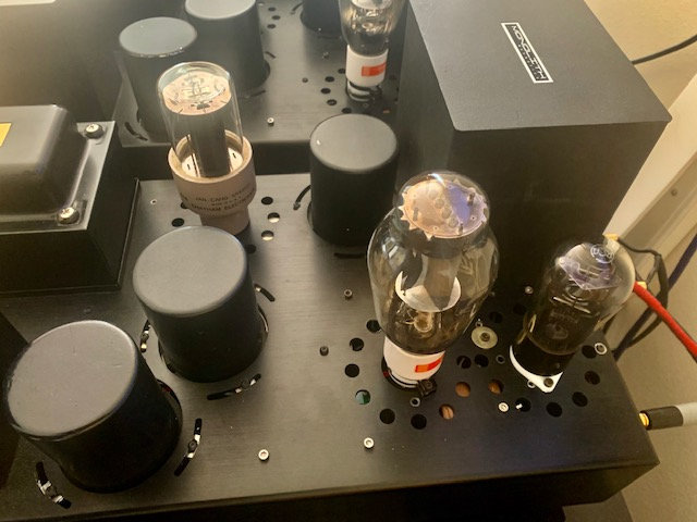
Today I finished off a 300b amp. Not optimised, but a decent build. Lundahl OPT, Rod Coleman regs on the filaments, cathode bias with large polypropylene bypasses. 2 stage, with a EF180 with a gyrator and SIC diode bias.
Not even in the ballpark with my PSE 4P1L build with 26 first stage. I abandoned 300b amps years ago and this hasn't really changed my conclusion that an all-DHT 2 stage amp with filament bias on the PSE 4P1Ls will out-sound a 2 stage 300b build with the inevitable indirectly heated driver.
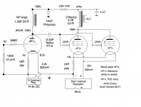
Here's my current 4P1L PSE:
What's that anode choke you use for first tube? I'm looking for something similar for 3A5 tube.
According to RDH 4 a negligible portion of the signal voltage will occur across the capacitor at all signal frequencies if its reactance is small at the lowest frequencies to be amplified. So, not much feedback.
ok , i'm not against new tricks , do you think it will also work to with 100K resistor and a grid choke instead of the interstage secondary ?
ok , i'm not against new tricks , do you think it will also work to with 100K resistor and a grid choke instead of the interstage secondary ?
No, it needs a floating output from the driver as in a transformer secondary that does not need to be referenced to ground.
No, it needs a floating output from the driver as in a transformer secondary that does not need to be referenced to ground.
ok , thanks for the info
andy do feel the 390R grid stopper is necessary with the 26 driver or the 300B
i know it is with high mu pentode like the 4P1L or 6E5P ..
26 and 300B
Last edited:
> do feel the 390R grid stopper is necessary with the 26 driver or the 300B
If the wires from the transformer are twisted, and the ground side is connected near to the valve-socket (the diodes-network should be wired compactly) - then no grid-stopper should be needed.
Test it with an AM radio, when the amp is playing big signals, and no signal.
If the wires from the transformer are twisted, and the ground side is connected near to the valve-socket (the diodes-network should be wired compactly) - then no grid-stopper should be needed.
Test it with an AM radio, when the amp is playing big signals, and no signal.
I went back to the 4P1L as a driver and was shocked at how much more detail there is than with the 26. Not as smooth, but the detail is very attractive. There can be a tiny bit of edginess to the 4P1L and putting 2 together isn't ideal, but listening right now I'm thinking the gains outweighs the losses. Need some more extended listening. The 4P1Ls need to be in filament bias - that's the smoothest they ever sounded for me. Could probably put some more volts/current through the first stage but it sounds nice as it is. I have separate PSUs for each stage.
Attachments
> do feel the 390R grid stopper is necessary with the 26 driver or the 300B
If the wires from the transformer are twisted, and the ground side is connected near to the valve-socket (the diodes-network should be wired compactly) - then no grid-stopper should be needed.
Test it with an AM radio, when the amp is playing big signals, and no signal.
Hello Rod,
Could you explain a little more.
Some people use a mobile phone or is that a different purpose?
Twisting the heater wiring you mean?
I read some people twist but once arrived at the socket they do something wrong and all the benefits are gone.
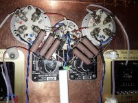
In the attachment my direct coupled E80cc/ VT25A single ended with your regulators for the power triodes. The E80cc is ac fed from a wire a few centimeters above the other parts but next to the bottomplate.
Greetings, Eduard
P.s i like the looks of the 310A i have some but only did put them in my tube tester to see the light!
Attachments
> Twisting the heater wiring you mean?
Twist the grid/ground wires from the IT to the driver valve. This reduces grid-anode coupling, in the hope that a grid stopper is not needed. Twist the wires up to the grid terminal on the socket. connect the grid. Then, make the shortest wire loop to ground.
> Some people use a mobile phone or is that a different purpose?
It's a test for oscillation. Take an AM (medium wave) battery-powered radio. Tune to a weak station somewhere around 150kHz - 1500kHz. Hold it near the valve, and power on the amplifier. If there is oscillation the radio will make a lot of noise or strange whining.
This way, you can remove the grid-stoppers, and test - one valve at a time.
Attachments
- Home
- Amplifiers
- Tubes / Valves
- One more 4P1L SE