Hi Ale;
I did not calculate equivalent L, it does not matter: what matters, is corner frequency. But if you want to, you can build an equivalent schematic, write an equation from it, then solve. It is simple: take an amp with finite amplification factor, take reactive capacitance and resistors, and solve for input impedance.
Anatoliy
Hi Anatoliy, any news on pse 4p1l yet?
Yes!
I had 7 tubes, bought from 2 different e-pay sellers from Ukraine. Measured all of them on -17V on first grid, 220V on anode. Idle currents are:
1. Feb 1966 50 mA
2. March 1976 42 mA
3. Feb 1966 45 mA
4. Feb 1966 44 mA
5. Feb 1966 41 mA
6. Feb 1966 43 mA
7. March 1976 50 mA
That means, differences in idle current on the same voltages is less than 10 percent.
I did not measure yet how well it performs, but Diana Krall sings very well, very real soundstage, I hear clear details. Obviously, output power is 5W per channel now, because when I connect the same 8 Ohm speakers to 16 Ohm taps, I see the same level on indicators.
Hi Ale;
I did not calculate equivalent L, it does not matter: what matters, is corner frequency. But if you want to, you can build an equivalent schematic, write an equation from it, then solve. It is simple: take an amp with finite amplification factor, take reactive capacitance and resistors, and solve for input impedance.
Anatoliy
Hi Anatoliy,
You lost me there. I thought it was the L what it matters. Why is the corner frequency what you need and how do you calculate it?
i may need to find a text covering this, as I haven't done any proper circuit analysis for more than 15 years, so will struggle with this :-(
cheers,
Ale
Just as clear as single tubes? The reason I ask is I am thinking of using 3 per channel, aiming for about 6.5w with low distortion and good damping factor
I am listening now to 2 per channel. Subjectively like more of highs, most probably because with the same transformers internal resistance of tubes in sum is twice lower, and twice lower is load resistance.
I am going to measure it later.
Hi Anatoliy,
You lost me there. I thought it was the L what it matters. Why is the corner frequency what you need and how do you calculate it?
i may need to find a text covering this, as I haven't done any proper circuit analysis for more than 15 years, so will struggle with this :-(
cheers,
Ale
Ale, R and C is enough to calculate dependence of output resistance on frequency; phase does not matter so no need to recalculate to an equivalent L.
You may assume an integrator around an amp with finite amplification factor, and current mode output. It is enough to select R and C values in ballpack with desired frequency response. I am not writing an article about science of gyrator; I am describing how I am toying with a small output amp with no negative feedback around it.
Last edited:
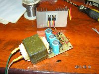
I can't stop listening, to measure... Just listening, and listening, and listening...
An externally hosted image should be here but it was not working when we last tested it.
大家好,我是来自中国的一位音响爱好者,无意中走进了该网站
虽然,我英语水平有限,但好在我用的谷歌浏览器可以帮我翻译
希望在这里跟大家交流,学习
请多关照!!!!!
歡迎
English, please!
Quote:
Originally Posted by GUOJIBAO Originally Posted by GUOJIBAO View Post
大家好,我是来自中国的一位音响爱好者,无意中走进了该网站 Hello everybody, I am from China, an audio enthusiast, accidentally walked into the site
虽然,我英语水平有限,但好在我用的谷歌浏览器可以帮我翻译 Although my English is limited, but fortunately I use the Google Chrome help me translate
希望在这里跟大家交流,学习 Want to share with you here, learning
请多关照! Best regards! ! ! ! ! ! ! ! !
歡迎 Welcome
Now I need a very clean 6.3V source, to power 6S17K-V tubes in MC phono corrector...
I will have both MC and MM correctors inside, with L-R correction.
This was going to be the next project I was looking at
")
A friend has offered to sell me his phono. ;-)
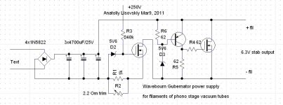
Here is chematic of power supply for filaments of phono stage tubes, It has to be very clean and separated, because 6S7K-V tubes have filaments connected to cathodes.
what is a chemantic?
don't open a door you cannot keep open.
dave
Interesting power supply for the 6S7K-V. Could you let us know what the active devices are.
I've been playing around with some 6S7K-Vs in a line stage, basically the Eric Barbour version with no cathode resistor. So far I like what I hear.
Perhaps this tube deserves its own thread.
ray
I've been playing around with some 6S7K-Vs in a line stage, basically the Eric Barbour version with no cathode resistor. So far I like what I hear.
Perhaps this tube deserves its own thread.
ray
what is a chemantic?
don't open a door you cannot keep open.
dave
What do you mean?
Interesting power supply for the 6S7K-V. Could you let us know what the active devices are.
I've been playing around with some 6S7K-Vs in a line stage, basically the Eric Barbour version with no cathode resistor. So far I like what I hear.
Perhaps this tube deserves its own thread.
Hi Ray;
In this stabilizer I am going to use 2SK1388 MOSFETs and 2N3702 BJT.
I rectify 12.6 to get clean 6.3V for filaments.
- Home
- Amplifiers
- Tubes / Valves
- One more 4P1L SE