Today I decided to punch more of holes on the chassis: to add 4P1L in parallel, and replace 6N16B in cathode followers by 6J9P.
An externally hosted image should be here but it was not working when we last tested it.


Today I decided to punch more of holes on the chassis: to add 4P1L in parallel, and replace 6N16B in cathode followers by 6J9P.
An externally hosted image should be here but it was not working when we last tested it.
Did you triode strap the 6J9Ps?
What cathode resistance?
TKS.
It is half of the story... The full story is to look at curves up to +16 volt on first grid (in one of my previous posts).
")
Did you triode strap the 6J9Ps?
What cathode resistance?
Everything is the same as in the original schematic, except 6J9P triode strapped instead of 6N16B with both triodes paralleled, plus one more 4P1L in parallel for 5W output per channel.
And output transformer with 2K primary, of course.
Questions re 4p1l PSE
I see some people have experienced some loss of clarity with PSE designs. Have you noticed anything like that with this one? Did you try to match the output pairs at all? Are you happy with the results? I have 10of these on the way and was thinking about trying them in push-pull, but I have also been tempted to try PSE as a simpler option.
I see some people have experienced some loss of clarity with PSE designs. Have you noticed anything like that with this one? Did you try to match the output pairs at all? Are you happy with the results? I have 10of these on the way and was thinking about trying them in push-pull, but I have also been tempted to try PSE as a simpler option.
Loss of clarity PSEI see some people have experienced some loss of clarity with PSE designs. Have you noticed anything like that with this one? Did you try to match the output pairs at all? Are you happy with the results? I have 10of these on the way and was thinking about trying them in push-pull, but I have also been tempted to try PSE as a simpler option.
and I just started a PSE design 
Loss of clarity PSE
I am scared to death too!

Nonsense
"I see some people have experienced some loss of clarity with PSE designs. Have you noticed anything like that ?"
I have also heard some people say that.
However Hiroyasu Kondo (Audio Note Japan), the famous designer Ongaku, has made several PSE amplifiers:
KSL NEIRO “The NEIRO is an 8-watt stereo amplifier. It uses parallel 2A3 output tubes”.
Kondo - Audio Note
KSL-KEGON 300B “The KSL-KEGON is a 300B based stereo amplifier. All Silver from input to output, It is in parallel single-ended operation with output of 20w per channel.”
You would think that Hiroyasu Kondo was wrong?
Some years ago there was an article by Norwood Still in Glass Audio or AudioXpress where he paralleled 5 x 12B4A per channel. I tried it out in a slightly different version and decided it was very clear.
To help ensure there wasn't current hogging, I had a cathode resistors on each tube.
So how about 10 x 4P1L per channel?
ray
To help ensure there wasn't current hogging, I had a cathode resistors on each tube.
So how about 10 x 4P1L per channel?
ray
Well, scared or not, how does it sound?
I did not finish it yet. But I don't think it will sound worse than 2A3 that has 2 paralleled triodes inside of the bulb.
So how about 10 x 4P1L per channel?
I am seriously thinking about 10 x 6J52P per channel. It should be a killing amp, with no driver needed.
I did not finish it yet. But I don't think it will sound worse than 2A3 that has 2 paralleled triodes inside of the bulb.
I suspect you are right about that..
Can't wait to get the quartet I ordered from Russia a couple of weeks ago. Small SE amp coming soon...
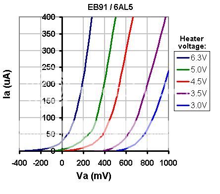
By the way, one explanation why interstage transformer, or direct coupling, is good to drive directly heated tubes, and interstage capacitor is bad: the higher is cathode emission, the more is grid current non-linear even when voltage on grid is negative. I've found this curves in the net, when the author was searching for better cathode temperature for double diode in guitar stomp box:
More parallel triodes
Conrad-Johnson ART Preamplifier
“…fabricating the equivalent of a single high-transconductance triode by linking five dual-triode 6922s in parallel” Conrad-Johnson ART Preamplifier | Stereophile.com
Tim de Paravicini EAR V20 amplifier
“With ten 12AX7s per channel, de Paravicini employs five tubes to cover each phase of the push-pull” EAR V20 integrated amplifier | Stereophile.com
The new Tim de Paravicini EAR V12 amplifier
“The V12 was designed by Tim de Paravicini and uses six EL84 tubes per channel. It puts our 50Wpc in triode mode”. E.A.R. V12 integrated amplifier | Stereophile.com
At the end...... Anatoly, what happens to your 4P1L PSE?
At the end...... Anatoly, what happens to your 4P1L PSE?
I will have results on Monday. Last Friday I soldered almost everything in output stages.
@wavebourn:
Cool!!
I am waiting with great anticipation!!! Hope to start on this project maybe by end of the month.... Trying to decide whether to go PSE or SE.... Still planning process and obtaining parts. Just got my sockets, but seems too tight to insert the tubes into.
Cool!!
I am waiting with great anticipation!!! Hope to start on this project maybe by end of the month.... Trying to decide whether to go PSE or SE.... Still planning process and obtaining parts. Just got my sockets, but seems too tight to insert the tubes into.
Gyrator
Hi Wavewourn,
Firstly thanks for continuously sharing your experience, I'm learning a lot from your posts!
i'm working on a 45SET at the moment and was looking at improving the 6SL7 driver stage from a typical resistor loaded grounded cathode configuration to an active loaded setup. I'm simulating at the moment a CCS using PNPs, but was keen to see any potential improvements by using a gyrator instead. Do you have any doc or share any link where I can get my head around how to calculate the values of the circuit you used?
thanks for your time
Ale
Hi!
I am listening now to stereo amp with... 2.5W per channel!
Sounds very clean. Stereo imaging is perfect. Even depth is heard well.
Output stage uses 4P1L DH tube, triode connected. Input stage uses triode connected 6J5P tube, loaded on gyrator for minimum tube distortions, green LED in cathode. It is coupled to 4P1L grid through cathode follower made on 6N16B with paralleled triodes, dynamically loaded on current source. It is not a "power drive", it is the way to minimize distortions caused by non-linear grid current, especially when interstage capacitor is used.
The whole thingy is powered from oversized PS with stabilized voltages for -56, +120, +240 and floating 6.3V.
Enjoy!
Hi Wavewourn,
Firstly thanks for continuously sharing your experience, I'm learning a lot from your posts!
i'm working on a 45SET at the moment and was looking at improving the 6SL7 driver stage from a typical resistor loaded grounded cathode configuration to an active loaded setup. I'm simulating at the moment a CCS using PNPs, but was keen to see any potential improvements by using a gyrator instead. Do you have any doc or share any link where I can get my head around how to calculate the values of the circuit you used?
thanks for your time
Ale
I'm simulating at the moment a CCS using PNPs, but was keen to see any potential improvements by using a gyrator instead. Do you have any doc or share any link where I can get my head around how to calculate the values of the circuit you used?
Hi Ale;
we already discussed gyrator load on this forum many times. I already answered the question about why I prefer gyrator, in this particular thread. You can find a lot of answers searching for gyrator keyword.
In short, gyrator in anode is CCS with servo. Servo works such a way so no matter how different are tubes, how old they are, how changed is their emission, servo keeps voltage on anode stable on DC adjusting idle current.
This particular servo I used is referenced to B+, it is the minus: PSRR on frequencies below audio band is low, so B+ source have to be well stabilized to avoid unwanted feedback and caused by it non-stability on ultra-low frequencies.
For better PSRR you may use version of Gyrator used by Michael Koster in his Meteor amp; also, the same MOSFET is used as a source follower, so it looks like SRPP stage with stable anode voltage.
Hi Wavebourn,
Thanks for this. I have been searching the web and also the forum and couldnt get hold of any formula to compute the equivalent L and circuit components of the mosfet gyrator, albeit I found many posts explaining benefits, caveats, etc.
Can you please explain how you calculated the gyrator in your circuit?
Thanks
Ale
- Home
- Amplifiers
- Tubes / Valves
- One more 4P1L SE